Lantronix xPico Wi-Fi Pi Plate User Guide - Page 7
Evaluation Kit, Table 2-1, Evaluation Board Connectors, Header and Switches
 |
View all Lantronix xPico Wi-Fi Pi Plate manuals
Add to My Manuals
Save this manual to your list of manuals |
Page 7 highlights
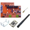
J1 Socket to PI board JP2 CP Header Antenna Cable 2: Evaluation Kit Figure 2-1 xPico Wi-Fi Raspberry Pi Connectors and Jumpers JP3 and JP5 Serial 1 Headers JP10 and JP11 3.3V and Ground JP17 Button Header Reset Button Default Button Wake Button JP6 Power Select J8 USB Device JP1 Current Sense J9 Serial 2 via USB JP J7 J8 J9 JP1 JP17 JP17 Table 2-1 Evaluation Board Connectors, Header and Switches Position 1-2 1-2 3-4 Label UUT PWR WLAN LED WAKE Function Default xPico module socket. Mini USB Type B connects to the xPico module USB device port. Note device port will be enabled on a future software release. Mini USB Type B connects to the xPico module serial port 2 through a USB to serial converter and the JP17 jumper headers. Connects to 0.301 ohm current sense resistor R1. Uninstalled Measure voltage on JP1 to calculate module power consumption Install to use WLAN LED Installed Install to use wake-up input and button,SW1 Installed xPico® Wi-Fi® Pi Plate User Guide 7
-
 1
1 -
 2
2 -
 3
3 -
 4
4 -
 5
5 -
 6
6 -
 7
7 -
 8
8 -
 9
9 -
 10
10 -
 11
11 -
 12
12 -
13
-
14
 |
 |
