Lantronix xPico Wi-Fi Pi Plate User Guide - Page 9
Antenna Port, Power Supply, LEDs, xPico® Wi-Fi® Pi Plate User Guide
 |
View all Lantronix xPico Wi-Fi Pi Plate manuals
Add to My Manuals
Save this manual to your list of manuals |
Page 9 highlights
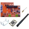
2: Evaluation Kit In order to access the unit through the J9 USB port, you will need to install the USB-to-serial VCP driver from FTDI on your PC. It is available in the installation directory of the Lantronix® DeviceInstaller™ utility, 4.3.0.2 and later versions, for installation. It can also be obtained from the FTDI website provided below. Once installed, you will be able to view the xPico boot messages as well as provide command inputs through any PC terminal program, such as Tera Term. Download FTDI USB-to-serial drivers at this website: http://www.ftdichip.com/Drivers/VCP.htm Antenna Port The xPico Wi-Fi Pi Plate includes a bracket for mounting the U.FL to reverse polarity SMA RF cable included with the kit. Follow the procedure below when installing the antenna cable. Connect the U.FL cable to the module Place the plastic retaining clip over the module Install the module into the socket. Install the external antenna to the SMA end of the RF cable. Note: Install or remove the module and antenna connections only while the module is powered off. Power Supply The Lantronix xPico Wi-Fi Pi Plate device is powered from the Raspberry Pi computer board when a jumper is installed to JP6 position 1 to 2. There is an option to power the board from the USB connectors when the board is run stand alone. If the board is run stand alone with no mating computer board, install the jumper on JP6 to position 2-3. LEDs The xPico evaluation board includes several LEDs for signal and unit status. The table below lists all of the LEDs and their functions. Table 2-2 LEDs Signals LED LED1/STATUS LED2/LINK JP17 1-2 Function Orange: LED blinks with patterns indicating module status. See the xPico Wi-Fi Embedded Device Server User Guide for a full description of the status LED blink patterns Orange: LED is ON when the device is associated with an access point (on the STA interface.) LED8/POWER Blue: 3.3V Power is on xPico® Wi-Fi® Pi Plate User Guide 9
-
 1
1 -
2
-
3
-
 4
4 -
 5
5 -
 6
6 -
 7
7 -
 8
8 -
 9
9 -
 10
10 -
 11
11 -
 12
12 -
 13
13 -
 14
14
 |
 |
