Lantronix xPico Wi-Fi Pi Plate User Guide - Page 8
Serial Port 1, Evaluation Kit, xPico® Wi-Fi® Pi Plate User Guide
 |
View all Lantronix xPico Wi-Fi Pi Plate manuals
Add to My Manuals
Save this manual to your list of manuals |
Page 8 highlights
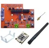
2: Evaluation Kit JP JP17 JP17 JP17 JP17 JP3 JP5 JP2 JP2 JP2 JP2 JP2 JP2 JP2 JP2 JP2 JP2 JP6 JP10 JP11 J1 Position 5-6 7-8 9-10 11-12 1-2 1-2 1-2 3-4 5-6 7-8 9-10 11-12 13-14 15-16 17-18 19-20 1-2 1-2 1-2 Label RXD2 TXD2 DEFAULTS RESET TX RX CP1 CP2 CP3 CP4 CP5 CP6 CP7 CP8 RTS1 CTS1 Power 3.3V GND Function Default Install to route xPico Wi-Fi module second serial port Installed to J9 via the on board USB to serial converter Install to route xPico Wi-Fi module second serial port Installed to J9 via the on board USB to serial converter Install to use Defaults input and button, SW2 Installed Install to use Hardware Reset input and button, SW3 Installed Install position 1-2 to connect xPico module TXD1 to Installed Raspberry Pi computer board serial RX. Install position 1-2 to connect xPico module RXD1 Installed to Raspberry Pi computer board serial TX. Breakout header for CP1 Installed Breakout header for CP2 Installed Breakout header for CP3 Installed Breakout header for CP4 Installed Breakout header for CP5 Installed Breakout header for CP6 Installed Breakout header for CP7 Installed Breakout header for CP8 Installed Header for RTS1, pin 18 does not connect anywhere Installed else on the board. Header for CTS1, pin 20 does not connect anywhere Installed else on the board. Install pins 1-2 to power plate board from Raspberry Installed Pi computer board 3.3V power generated by the on board regulator Not installed Board signal ground. Not installed Connector to mate to Raspberry Pi computer board. See schematic below. Serial Port 1 Serial port 1 of the xPico Wi-Fi embedded device server has the signals TXD1, RXD1. These signals are connected to the serial port on the Raspberry Pi computer board through JP3 and JP5. The RTS1 and CTS1 signals connect to header JP2, but do not connect to the Raspberry Pi computer board. xPico Wi-Fi Pin RXD1 (7) TXD1 (10) Raspberry Pi Pin JP3,JP5: 1-2 PI_TX1 (J1 pin 8) PI_RX1 (J1 pin 10) Serial Port 2 Serial port 2 of the xPico Wi-Fi device has the signals TXD2 and RXD2. These signals go through jumpers JP17 pins 5 to 6 and 7 to 8. If the jumpers are installed the serial port is routed to an onboard USB to serial converter, which then connects to USB connector J9 on the board. xPico® Wi-Fi® Pi Plate User Guide 8
-
 1
1 -
2
-
 3
3 -
 4
4 -
 5
5 -
 6
6 -
 7
7 -
 8
8 -
 9
9 -
 10
10 -
 11
11 -
 12
12 -
 13
13 -
14
 |
 |
