Lenovo 0319A25 User Manual
Lenovo 0319A25 Manual
 |
View all Lenovo 0319A25 manuals
Add to My Manuals
Save this manual to your list of manuals |
Lenovo 0319A25 manual content summary:
- Lenovo 0319A25 | User Manual - Page 1
Hardware Maintenance Manual ThinkPad Edge 14², Edge 15², E40, and E50 - Lenovo 0319A25 | User Manual - Page 2
and the product it supports, be sure to read the general information under Appendix A "Notices" on page 155. Fourth Edition (December 2011) © Copyright Lenovo 2010, 2011. LIMITED AND RESTRICTED RIGHTS NOTICE: If products, data, computer software, and services are delivered pursuant a General - Lenovo 0319A25 | User Manual - Page 3
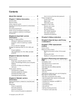
27 What to do first 27 Checkout guide 28 Diagnostics using PC-Doctor for DOS. . . . 28 Lenovo ThinkVantage Toolbox (Lenovo System Toolbox 31 PC-Doctor for Rescue No-beep symptoms 42 LCD-related symptoms 42 Intermittent problems 42 Undetermined problems 43 Chapter 5. Status indicators . . . . - Lenovo 0319A25 | User Manual - Page 4
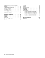
Premium (32 bit) DVDs . . 149 Windows 7 Home Premium (64 bit) DVDs . . 150 Windows 7 Professional (32 bit) DVDs. . . . 151 Windows 7 Professional (64 bit) DVDs. . . . 152 Common service tools 153 Appendix A. Notices 155 Trademarks 156 ii Hardware Maintenance - Lenovo 0319A25 | User Manual - Page 5
manual contains service and reference information for the following ThinkPad® Notebook products. ThinkPad Edge 14" and E40 ThinkPad Edge 15" and E50 Machine types (MT) 0199, 0578, and 0579 MT 0301, 0302, and 0319 Use this manual along with the advanced diagnostic tests to troubleshoot problems - Lenovo 0319A25 | User Manual - Page 6
iv Hardware Maintenance Manual - Lenovo 0319A25 | User Manual - Page 7
you need to be familiar with before you service a ThinkPad Notebook. • "General safety" on page 1 • "Electrical safety" on page 2 • "Safety inspection guide" on page 3 • "Handling devices that are Do not obstruct fan louvers or cover them with labels or stickers. © Copyright Lenovo 2010, 2011 1 - Lenovo 0319A25 | User Manual - Page 8
-off (EPO) switch, disconnecting switch, or electrical outlet. If an electrical accident occurs, you can then operate you work with very high voltages; Instructions for these precautions are in the personal injury and machine damage. • Do not service the following parts with the power on when they - Lenovo 0319A25 | User Manual - Page 9
to attachment of non-ThinkPad features or options not covered by this inspection guide. If any unsafe service task. Begin the checks with the power off, and the power cord disconnected. Checklist: 1. Check exterior covers for damage (loose, broken, or sharp edges). 2. Power off the computer - Lenovo 0319A25 | User Manual - Page 10
, to provide protection that meets the specific service requirement. Note: The use of a grounding computers. Grounding requirements Electrical grounding of the computer is required for operator safety and correct system function. Proper grounding of the electrical outlet Hardware Maintenance Manual - Lenovo 0319A25 | User Manual - Page 11
DANGER DANGER DANGER DANGER DANGER DANGER Chapter 1. Safety information 5 - Lenovo 0319A25 | User Manual - Page 12
DANGER 6 Hardware Maintenance Manual - Lenovo 0319A25 | User Manual - Page 13
PERIGO PERIGO PERIGO Chapter 1. Safety information 7 - Lenovo 0319A25 | User Manual - Page 14
PERIGO PERIGO PERIGO PERIGO PERIGO 8 Hardware Maintenance Manual - Lenovo 0319A25 | User Manual - Page 15
DANGER DANGER DANGER DANGER DANGER Chapter 1. Safety information 9 - Lenovo 0319A25 | User Manual - Page 16
DANGER DANGER DANGER VORSICHT VORSICHT 10 Hardware Maintenance Manual - Lenovo 0319A25 | User Manual - Page 17
VORSICHT VORSICHT VORSICHT VORSICHT VORSICHT VORSICHT Chapter 1. Safety information 11 - Lenovo 0319A25 | User Manual - Page 18
12 Hardware Maintenance Manual - Lenovo 0319A25 | User Manual - Page 19
Chapter 1. Safety information 13 - Lenovo 0319A25 | User Manual - Page 20
14 Hardware Maintenance Manual - Lenovo 0319A25 | User Manual - Page 21
Chapter 1. Safety information 15 - Lenovo 0319A25 | User Manual - Page 22
16 Hardware Maintenance Manual - Lenovo 0319A25 | User Manual - Page 23
Laser compliance statement (multilingual translations) The laser compliance statements in this section are provided in the following languages: • English • Arabic • Brazilian Portuguese • French • German • Hebrew • Japanese • Korean • Spanish • Traditional Chinese Chapter 1. Safety information 17 - Lenovo 0319A25 | User Manual - Page 24
18 Hardware Maintenance Manual - Lenovo 0319A25 | User Manual - Page 25
Chapter 1. Safety information 19 - Lenovo 0319A25 | User Manual - Page 26
20 Hardware Maintenance Manual - Lenovo 0319A25 | User Manual - Page 27
Chapter 1. Safety information 21 - Lenovo 0319A25 | User Manual - Page 28
22 Hardware Maintenance Manual - Lenovo 0319A25 | User Manual - Page 29
in this manual. After a system board is replaced, ensure that the latest BIOS is loaded to the system board before completing the service action. To download software fixes, drivers, and BIOS, do as follows: 1. Go to http://support.lenovo.com. 2. Enter the product number of the computer or press - Lenovo 0319A25 | User Manual - Page 30
symptom is listed in the Symptom-to-FRU Index for the computer you are servicing. Strategy for replacing FRUs for CTO, CMV, and GAV Model Variant (CMV) This is a unique configuration that has been negotiated between Lenovo and the customer. A unique 4-digit MT and 3-digit model is provided to Manual - Lenovo 0319A25 | User Manual - Page 31
the following Web site: http://support.lenovo.com • To view the key commodities, do the following: 1. Click Products & Service Warranty. 2. Click Check follow the instructions on the screen to reach the Product and Parts Details page. 2. Click the Parts Detail tab to view the list of service parts. - Lenovo 0319A25 | User Manual - Page 32
Use the HMM as a backup to PEW and eSupport to view the complete list of FRUs at the MT model level. 26 Hardware Maintenance Manual - Lenovo 0319A25 | User Manual - Page 33
ThinkPad model that supports the PC-Doctor® for DOS diagnostics program. Some descriptions might not apply to your particular computer. Before you go to the checkout guide, be sure to read the following important notes. Important: • Only certified trained personnel should service the computer problem - Lenovo 0319A25 | User Manual - Page 34
the following Web site: http://support.lenovo.com • To create the PC-Doctor diagnostic CD, follow the instructions on the Web site. For some possible configurations of the computer, PC-Doctor might not run correctly. To avoid this problem, you need to initialize the computer setup by use of the BIOS - Lenovo 0319A25 | User Manual - Page 35
available on the following Web site: http://support.lenovo.com Testing the computer Note: The PC-Doctor for DOS CD-R/CD-RW disc supports only test of internal optical disc drives (CD-RW, CD-RW/DVD Combo, and DVD Multi drives) on ThinkPad computers. It does not support test of any optical disc drives - Lenovo 0319A25 | User Manual - Page 36
ThinkPad Notebook. If you have an external monitor attached to the computer, detach it before running PC-Doctor for DOS. • To test Digital Signature Chip, the security chip must be set to Active. 10. Run the applicable function test. 11. Follow the instructions on the screen. If there is a problem - Lenovo 0319A25 | User Manual - Page 37
on the computer, follow the instructions on the Web site. To run this program, do as follows: Click Start ➙ Control Panel ➙ System and Security ➙ Lenovo's System Health and Diagnostics. Follow the instructions on the screen. Lenovo ThinkVantege Toolbox (Lenovo System Toolbox) also has problem - Lenovo 0319A25 | User Manual - Page 38
. 5. Turn off the computer. 6. Disconnect the ac adapter and install the charged battery pack. 7. Check that the battery pack supplies power when you turn on the computer. If you suspect a power problem, see the appropriate one of the following power supply checkouts: 32 Hardware Maintenance Manual - Lenovo 0319A25 | User Manual - Page 39
correct continuity and installation. • If the computer does not charge during operation, go to of the ac adapter may different from the one you are servicing. 3. If the voltage is not correct, replace the ac adapter • Replace the system board. • If the problem persists, go to "FRU tests" on page - Lenovo 0319A25 | User Manual - Page 40
Note: If the battery pack becomes hot, it may not be able to charge. Remove it from the computer and leave it at room temperature for a while. After it cools down, reinstall and recharge it. To battery discharges quickly after replacement, replace the system board. 34 Hardware Maintenance Manual - Lenovo 0319A25 | User Manual - Page 41
" on page 148. The recovery disc set consists of the user instructions and the following set of DVDs to restore the computer to the original factory configuration. Operating System Recovery Disc (one disc) Applications and Drivers Recovery Disc (one or more discs) Supplemental Recovery Disc This - Lenovo 0319A25 | User Manual - Page 42
Utility. Note: After restoring a drive to the factory default settings, you might need to reinstall some device drivers. Passwords As many as three passwords may be needed for any ThinkPad Notebook: the power-on password (POP), the hard-disk password (HDP), and the supervisor password (SVP). If - Lenovo 0319A25 | User Manual - Page 43
service technician: 1. Turn on the computer. 2. When the ThinkPad logo comes up, immediately press F1 to enter BIOS Setup Utility.For models supporting be made available to the service technician, neither Lenovo nor Lenovo authorized service technicians provide any services to reset the user HDPs - Lenovo 0319A25 | User Manual - Page 44
computer. 2. When the ThinkPad logo comes up, immediately press F1 to enter BIOS Setup Utility.For models supporting ThinkPad Notebook you are servicing supports computer has three power management modes: screen blank, sleep, and hibernation. Screen blank mode To put the computer computer computer - Lenovo 0319A25 | User Manual - Page 45
the problem, put the original part back in the computer. Do not replace a nondefective FRU. This index can also help you determine, during regular servicing, what "Intermittent problems" on page 42. Note: For a device not supported by diagnostic codes in the ThinkPad Notebooks, see the manual for - Lenovo 0319A25 | User Manual - Page 46
3. System board. 0271 Date and time error-Neither the date nor the time is set in the computer. (two short beeps) Run BIOS Setup Utility to reset the time and date. 0280 Previous boot incomplete 02F5 DMA test failed. (two short beeps) 1. DIMM. 2. System board. 40 Hardware Maintenance Manual - Lenovo 0319A25 | User Manual - Page 47
Enter to load the default setting. Then save the current setting by pressing F10, and restart the computer. 1. Fan. 2. Thermal grease. 3. System board. Memory card is not installed. Install memory current setting by pressing F10, and restart the computer. Chapter 4. Related service information 41 - Lenovo 0319A25 | User Manual - Page 48
the notebook computer contains many servicing has two or less visible defective pixels, it should not be considered faulty. However, if the LCD has three or more visible defective pixels, it will be deemed as defective by Lenovo and it should be replaced. Notes: • This policy applies to all ThinkPad - Lenovo 0319A25 | User Manual - Page 49
are supported by the computer. ThinkPad devices b. Printer, mouse, and other external devices c. Battery pack d. Hard disk drive e. External diskette drive or optical drive f. DIMM g. Optical disk or diskette in the internal drive h. PC Cards 4. Turn on the computer. 5. Determine whether the problem - Lenovo 0319A25 | User Manual - Page 50
44 Hardware Maintenance Manual - Lenovo 0319A25 | User Manual - Page 51
this indicator is on. The ac adapter is not connected. The illumination dot in the ThinkPad logo on the outer lid of the computer and on the palm rest works as a system-status indicator: it shows whether the computer is in sleep (standby), hibernation, or normal model. Red: Fast blinking red: The - Lenovo 0319A25 | User Manual - Page 52
Meaning Slow blinking red: Off: On-screen indicators Caps lock: Wireless status: The computer is in sleep (standby) mode. The computer is off or in hibernation mode. Caps Lock mode is enabled. You can enter change the power state of each feature in the list. 46 Hardware Maintenance Manual - Lenovo 0319A25 | User Manual - Page 53
is also available. The computer display becomes dimmer. The purpose of this method is to change the brightness level temporarily. To change the default brightness level, change the settings of the Power Option in the Control Panel or use the Power Manager. © Copyright Lenovo 2010, 2011 47 - Lenovo 0319A25 | User Manual - Page 54
following device drivers must be installed on the computer beforehand: • Power Management driver • OnScreen Display Utility • Wireless device drivers Fn + Spacebar computer off, put it in sleep or hibernation mode, the keyboard illumination setting is reset of "Off". 48 Hardware Maintenance Manual - Lenovo 0319A25 | User Manual - Page 55
is your responsibility; you may request that Lenovo installs an Optional-service CRU according to the warranty service for your product. Where you are installing the CRU, Lenovo will ship the CRU to you. CRU information and replacement instructions are shipped with your product and are available - Lenovo 0319A25 | User Manual - Page 56
firmly. • Ensure torque screw drivers are calibrated correctly following country LENOVO ThinkPad Hardware Maintenance Diskette Version 1.76 or later and restart the computer. 2. From the main menu, select 1. Set System Identification. 3. Select 1. Add S/N data from EEPROM. Follow the instructions - Lenovo 0319A25 | User Manual - Page 57
or later. 1. Insert the LENOVO ThinkPad Hardware Maintenance Diskette Version 1.76 or later, and restart the computer. 2. From the main menu, select 6. Set ECA Information. 3. To read ECA information, select 2. Read ECA/rework number from EEPROM and follow the instruction. 4. To read box build date - Lenovo 0319A25 | User Manual - Page 58
52 Hardware Maintenance Manual - Lenovo 0319A25 | User Manual - Page 59
Lenovo installs an Optional-service CRU according to the warranty service for your product. Where you are installing the CRU, Lenovo will ship the CRU to you. CRU information and replacement instructions , turn off the computer, unplug all power cords from electrical outlets, remove the battery pack - Lenovo 0319A25 | User Manual - Page 60
is physically damaged or a customer is reporting a possible safety issue. If Lenovo ThinkVantage Toolbox is not installed in the computer, the customer should download this program before a non-physically damaged battery pack this FRU: • "1010 Battery pack" on page 54 54 Hardware Maintenance Manual - Lenovo 0319A25 | User Manual - Page 61
Table 9. Removal steps of optical drive or travel cover 1 Step 1 Screw (quantity) M2 × 8 mm, wafer-head, nylon-coated (1) 2 3 Color Black Torque 0.181 Nm (1.85 kgfcm) 1030 Thermal cover For access, remove this FRU: • "1010 Battery pack" on page 54 Chapter 8. Removing and replacing a FRU 55 - Lenovo 0319A25 | User Manual - Page 62
the fan motor located in the slot. It might cause damage to the fan assembly or the computer to mulfunction. 1040 Hard disk drive (HDD) assembly For access, remove these FRUs in order: possible. • Never remove the drive while the computer is operating or is in suspend mode. 56 Hardware Maintenance - Lenovo 0319A25 | User Manual - Page 63
Table 11. Removal steps of HDD assembly 1 When installing: Make sure that the HDD connector is attached firmly. 2 a When installing: Do not apply excessive force to the HDD bracket a . To do so, you might bend or break it. 1050 DIMM For access, remove these FRUs in order: • "1010 Battery pack" on - Lenovo 0319A25 | User Manual - Page 64
Table 12. Removal steps of DIMM 1 2 1 Note: If only one DIMM is used on the computer you are servicing, the card must be installed in SLOT-0 ( a : lower slot), but not in SLOT-1 ( b : motor. It might cause damage to the fan assembly or the computer to mulfunction. 58 Hardware Maintenance Manual - Lenovo 0319A25 | User Manual - Page 65
. Note: Loosen the screws 2a to 2f in order, but do not remove them. When you attach the fan, secure the screws in order. For Thinkpad Edge 15" and E50: 2c 2b 3 2a 2e 2d 2f For ThinkPad Edge 14" and E40: Chapter 8. Removing and replacing a FRU 59 - Lenovo 0319A25 | User Manual - Page 66
Note: Step 3 is only for ThinkPad Edge 15". For ThinkPad Edge 14", skip step 3 . Step 3 Screw (quantity) M2 × 4 mm, wafer-head, nylon-coated (1) Color Silver Torque 0.181 Nm (1.85 kgfcm) 4 When installing: Before you attach the fan assembly to the computer, apply thermal grease, at an amount - Lenovo 0319A25 | User Manual - Page 67
: • "1010 Battery pack" on page 54 • "1030 Thermal cover" on page 55 • "1060 Fan assembly" on page 58 Attention: CPU is extremely sensitive. When you service the CPU, avoid any kind of rough handling. Chapter 8. Removing and replacing a FRU 61 - Lenovo 0319A25 | User Manual - Page 68
WAN slot cover and PCI Express Mini Card for wireless WAN For access, remove this FRU: • "1010 Battery pack" on page 54 62 Hardware Maintenance Manual - Lenovo 0319A25 | User Manual - Page 69
Table 15. Removal steps of wireless WAN slot cover and PCI Express Mini Card for wireless WAN Note: Loosen the screw 1 , but do not remove it. 1 2 In - Lenovo 0319A25 | User Manual - Page 70
(quantity) M2 × 3 mm, wafer-head, nylon-coated (2) Color Black Torque 0.181 Nm (1.85 kgfcm) 5 Table 16. Removal steps of SIM card Some models of ThinkPad Edge 14", Edge 15", E40, and E50 might have the SIM card that the customer has been installed. If you need to replace the system board in those - Lenovo 0319A25 | User Manual - Page 71
Table 16. Removal steps of SIM card (continued) 3 2 1090 Palm rest assembly with cables For access, remove these FRUs in order: • "1010 Battery pack" on page 54 • "1020 Optical drive or travel cover" on page 54 Note: In models with the fingerprint reader, the sensor is attached to the palm rest FRU. - Lenovo 0319A25 | User Manual - Page 72
Table 17. Removal steps of palm rest assembly with cables (continued) 2 M2 × 3 mm, wafer-head, nylon-coated (1) Black 0.181 Nm (1.85 kgfcm) 3 4 5 3 7 6 7 6 66 Hardware Maintenance Manual - Lenovo 0319A25 | User Manual - Page 73
the cables to the system board firmly. 2. Attach the palm rest so that the two small projections of the palm rest firmly fit into the guide holes of the keyboard bezel as shown in this figure. 3. Push the front side of the palm rest until it clicks into place. 4. Close the - Lenovo 0319A25 | User Manual - Page 74
direction of the arrow. 1b 1a 2 2 Step 2 Screw (quantity) M2 × 3 mm, wafer-head, nylon-coated (2) Color Black Torque 0.181 Nm (1.85 kgfcm) 68 Hardware Maintenance Manual - Lenovo 0319A25 | User Manual - Page 75
cover" on page 54 • "1090 Palm rest assembly with cables" on page 65 DANGER Use only the battery specified in the parts list for your computer. Any other battery could ignite or explode. Chapter 8. Removing and replacing a FRU 69 - Lenovo 0319A25 | User Manual - Page 76
pack" on page 54 • "1020 Optical drive or travel cover" on page 54 • "1090 Palm rest assembly with cables" on page 65 70 Hardware Maintenance Manual - Lenovo 0319A25 | User Manual - Page 77
Table 21. Removal steps of BDC-2 1 2 Step 1 Screw (quantity) M2 × 3 mm, wafer-head, nylon-coated (1) Color Black Torque 0.181 Nm (1.85 kgfcm) When installing: Make sure that the connector on bottom side of the card is attached firmly to the system board. 1130 Keyboard For access, remove these - Lenovo 0319A25 | User Manual - Page 78
) M2 × 5 mm, wafer-head, nylon-coated (1) Color Black Torque 0.181 Nm (1.85 kgfcm) 2 3 2 4 5 Step 6 Screw (quantity) M2 × 3 mm, wafer-head, nylon-coated (1) 72 Hardware Maintenance Manual Color Black Torque 0.181 Nm (1.85 kgfcm) - Lenovo 0319A25 | User Manual - Page 79
Table 23. Installation of the keyboard 1. Attach the connectors. 2. Attach the keyboard so that the keyboard edges are under the frame as shown in this figure. 3. To make sure that the front side of the screws from the bottom side of the computer. Chapter 8. Removing and replacing a FRU 73 - Lenovo 0319A25 | User Manual - Page 80
.5 × 6.5 mm, wafer-head, nylon-coated (2) M2 × 3 mm, wafer-head, nylon-coated (5) Color Black Black Torque 0.392 Nm (4 kgfcm) 0.181 Nm (1.85 kgfcm) 74 Hardware Maintenance Manual - Lenovo 0319A25 | User Manual - Page 81
Table 24. Removal steps of keyboard bezel (continued) 3 6 3 4 5 Step 3 Screw (quantity) M2 × 3 mm, wafer-head, nylon-coated (2) Color Black Torque 0.181 Nm (1.85 kgfcm) When installing: Make sure that the connectors are attached firmly to the system board. Chapter 8. Removing and replacing - Lenovo 0319A25 | User Manual - Page 82
68 • "1130 Keyboard" on page 71 • "1140 Keyboard bezel" on page 74 Table 25. Removal steps of LCD unit Step Screw (quantity) 76 Hardware Maintenance Manual 1 1 Color Torque - Lenovo 0319A25 | User Manual - Page 83
attached firmly to the system board. In step 4 , release wireless antenna cables from the cable guides. 4 4 4 4 4 4 4 4 4 4 4 When installing: Make sure that the cables are attached to the cable guides firmly . Attention: When you route the cables, make sure that they are not subjected to - Lenovo 0319A25 | User Manual - Page 84
of LCD unit (continued) Steps 5a are for ThinkPad Edge 14" and E40, and steps 5b are for ThinkPad Edge 15" and E50. 5a 5b 5a 5b 5a 5a 5b 5b Step 5a or 5b Screw (quantity) M2.5 × 6.5 mm, wafter-head, nylon-coated (4) Color Black Torque 0.392 Nm (4 kgfcm) 78 Hardware Maintenance Manual - Lenovo 0319A25 | User Manual - Page 85
Keyboard" on page 71 • "1140 Keyboard bezel" on page 74 • "1150 LCD unit" on page 76 Table 26. Removal steps of top shielding assembly For ThinkPad Edge 15" and E50: Chapter 8. Removing and replacing a FRU 79 - Lenovo 0319A25 | User Manual - Page 86
2 3 Screw (quantity) M2 × 2 mm, wafer-head, nylon-coated (3) M2 × 3 mm, wafer-head, nylon-coated (5) M2 × 5 mm, wafer-head, nylon-coated (2) For ThinkPad Edge 14" and E40: 1 2 2 3 3 3 3 4 Color Silver Black Black Torque 0.181 Nm (1.85 kgfcm) 0.181 Nm (1.85 kgfcm) 0.181 Nm (1.85 kgfcm) Step - Lenovo 0319A25 | User Manual - Page 87
Protection System still functions. The procedure is as follows: 1. Place the computer on a horizontal surface. 2. Run Diagnostics ➙ ThinkPad Devices ➙ HDD Active Protection Test. Attention: Do not apply physical shock to the computer while the test is running. For access, remove these FRUs, in - Lenovo 0319A25 | User Manual - Page 88
are extremely sensitive. When you service the system board, avoid any kind of rough handling. a GMCH (Integrated video chip) b CPU c ICH (I/O Controller Hub) d Video chip (only for discrete models) For ThinkPad Edge 14" and E40 integrated models: a b For ThinkPad Edge 14" and E40 discrete - Lenovo 0319A25 | User Manual - Page 89
of major sensitive components on the system board (continued) For ThinkPad Edge 15" and E50 integrated models: a b c For ThinkPad Edge 15" and E50 discrete models: a b d Table 28. Removal steps of system board assembly For ThinkPad Edge 15" and E50: c 11 1 1 Step Screw (quantity) Color Torque - Lenovo 0319A25 | User Manual - Page 90
Table 28. Removal steps of system board assembly (continued) 1 M2 × 5 mm, wafer-head, nylon-coated (4) For ThinkPad Edge 14" and E40: 1 1 Black 0.181 Nm (1.85 kgfcm) Step 1 Screw (quantity) M2 × 5 mm, wafer-head, " on page 54 • "1030 Thermal cover" on page 55 84 Hardware Maintenance Manual - Lenovo 0319A25 | User Manual - Page 91
firmly. Step 2 Screw (quantity) M2 × 3 mm, wafer-head, nylon-coated (1) Color Black Cable routing: Route the USB cable assembly as shown in these figures. For ThinkPad Edge 15" and E50: Torque 0.181 Nm (1.85 kgfcm) For ThinkPad Edge 14" and E40: Chapter 8. Removing and replacing a FRU 85 - Lenovo 0319A25 | User Manual - Page 92
Top shielding assembly" on page 79 • "1170 System board assembly" on page 81 Table 30. Removal steps of DC-in cable and base cover For ThinkPad Edge 15" and E50: 86 Hardware Maintenance Manual - Lenovo 0319A25 | User Manual - Page 93
steps of DC-in cable and base cover (continued) 4 3 1 2 Step 1 Screw (quantity) M2 × 3 mm, wafer-head, nylon-coated (2) Color Black For ThinkPad Edge 14" and E40: 1 2 4 3 Torque 0.181 Nm (1.85 kgfcm) Step 1 Screw (quantity) M2 × 5 mm, wafer-head, nylon-coated (1) Color Black Torque 0.181 - Lenovo 0319A25 | User Manual - Page 94
and base cover (continued) Cable routing: Route the cable as shown in these figures. For ThinkPad Edge 15" and E50: For ThinkPad Edge 14" and E40: Applying labels to the base cover The new base cover FRU is shipped MAC address label 2 Wireless WAN MAC address label 88 Hardware Maintenance Manual - Lenovo 0319A25 | User Manual - Page 95
them in the label kit and apply them to the new base cover. For the location of each label, refer to the following figures: For ThinkPad Edge 15" and E50: 1 2 3 4 12 5 11 6 7 10 9 8 Chapter 8. Removing and replacing a FRU 89 - Lenovo 0319A25 | User Manual - Page 96
For ThinkPad Edge 14" and E40: 1 2 3 4 12 5 11 6 7 10 9 8 2010 LCD front bezel For access, remove these FRUs in order: • "1010 1 1 1 1 Step 1 Screw cap Screw (quantity) M2 × 5 mm, wafer-head, nylon-coated (4) Color Black 90 Hardware Maintenance Manual Torque 0.181 Nm (1.85 kgfcm) - Lenovo 0319A25 | User Manual - Page 97
Table 31. Removal steps of LCD front bezel (continued) 22 2 2 2 2 2 22 When installing: Make sure that all the latches are attached firmly. Then secure the bezel with the screws. 2020 Speaker assembly For access, remove these FRUs in order: • "1010 Battery pack" on page 54 • "1080 Wireless - Lenovo 0319A25 | User Manual - Page 98
" on page 71 • "1140 Keyboard bezel" on page 74 • "1150 LCD unit" on page 76 • "2010 LCD front bezel" on page 90 92 Hardware Maintenance Manual - Lenovo 0319A25 | User Manual - Page 99
. Removal steps of hinges, LCD panel, LCD cable, and LCD rear cover assembly For ThinkPad Edge 15" and E50: 1 1 11 2 2 2 2 Step 1 Screw (quantity) M2 × 5 mm, wafer-head, nylon-coated (4) For ThinkPad Edge 14" and E40: 1 Color Black Torque 0.181 Nm (1.85 kgfcm) 1 Step 1 Screw (quantity) M2 - Lenovo 0319A25 | User Manual - Page 100
Table 34. Removal steps of hinges, LCD panel, LCD cable, and LCD rear cover assembly (continued) 3 4 5 6 7 94 Hardware Maintenance Manual - Lenovo 0319A25 | User Manual - Page 101
Table 34. Removal steps of hinges, LCD panel, LCD cable, and LCD rear cover assembly (continued) 3 4 3 3 4 3 Step 3 Screw (quantity) M2 × 3 mm, small-head, nylon-coated (4) Color Black When installing: Make sure that the LCD connector is attached firmly. Torque 0.181 Nm (1.85 kgfcm) 2050 - Lenovo 0319A25 | User Manual - Page 102
Table 35. Removal steps of antenna assembly Release the antenna cables from the cable guides of the LCD rear cover assembly and from the hinges. 2 2 1 1 1 1 1 1 1 1 When Tension could cause the cables to be damaged by the cable guides, or a wire to be broken. 96 Hardware Maintenance - Lenovo 0319A25 | User Manual - Page 103
Chapter 9. Locations This chapter presents the location of ThinkPad Edge 14", Edge 15", E40, and E50 features and hardware. Front view 1 Integrated camera 2 Touch pad buttons 13 Touch pad 14 TrackPoint buttons 15 TrackPoint pointing stick 16 UltraNav® © Copyright Lenovo 2010, 2011 97 - Lenovo 0319A25 | User Manual - Page 104
1 2 3 15 14 13 16 120 11 3 4 5 6 7 8 10 9 Rear view 1 Sleep (standby) status indicator Note: For the description of the 2 Combo audio jack 3 HDMI port 4 RJ-45 (Ethernet) connector 5 eSATA/USB connector 6 External monitor connector 1 98 Hardware Maintenance Manual 2 3 4 5 6 - Lenovo 0319A25 | User Manual - Page 105
Bottom view 1 Battery pack 2 Battery pack latch 3 Thermal slot (DIMM, hard disk drive, fan assembly) 4 Wireless WAN card slot 5 Media Card Reader 1 2 5 4 3 Chapter 9. Locations 99 - Lenovo 0319A25 | User Manual - Page 106
100 Hardware Maintenance Manual - Lenovo 0319A25 | User Manual - Page 107
.lenovo.com/CRUs. You may be required to return the defective part that is replaced by the CRU. When return is required: (1) return instructions CRU. See your Lenovo Limited Warranty documentation for full details. ThinkPad computers contain the following types of CRUs: - Self-service CRUs: These - Lenovo 0319A25 | User Manual - Page 108
Overall 1 22 21 2 20 3 19 18 4 17 5 16 15 14 13 6 12 7 11 8 9 10 102 Hardware Maintenance Manual - Lenovo 0319A25 | User Manual - Page 109
Table 36. Parts list-Overall No. FRU (Overall) FRU no. CRU ID 1 LCD unit (see "LCD FRUs" on page 130.) 2 Keyboard bezel assembly 14W 60Y5597 N 2 Keyboard bezel assembly 15W 60Y5599 N 3 Top shielding assembly 14W 75Y6120 N 3 Top shielding assembly for 0199 04W0273 N 3 Top shielding - Lenovo 0319A25 | User Manual - Page 110
, 7Bx, 7Cx, 7Dx, 7Ex, 7Mx, 7Rx, 7Sx, 83x, 84x, J2x, JAx, JBx, KSx, NQx, PDx • 0579-CTO FRU no. 55Y3715 CRU ID ** 104 Hardware Maintenance Manual - Lenovo 0319A25 | User Manual - Page 111
Table 36. Parts list-Overall (continued) No. FRU (Overall) 4 2-GB DDR3-1333 SDRAM SO-DIMM (PC3-10600) card • 0199-CTO • 0301-CTO, 22x, 23x, 24x, 25x, 26x, 27x, 28x, 29x, 2Ax, 2Bx, 2Cx, 2Dx, 2Ex, 2Fx, 2Gx, 2Hx, 2Jx, 2Kx, 2Lx, 2Mx, 2Nx, 2Px, 2Qx, 2Rx, 2Sx, 2Tx, 2Ux, 2Vx, 2Wx, 2Xx, 2Yx, 2Zx, 33x, 34x, - Lenovo 0319A25 | User Manual - Page 112
, AFx, AGx, AHx, AJx, AKx, ALx, AMx, ANx, APx, CPx, CRx, CUx, CVx, CWx, CXx, CYx, D4x, D5x, D6x, D7x, D8x, DJx, 106 Hardware Maintenance Manual - Lenovo 0319A25 | User Manual - Page 113
Table 36. Parts list-Overall (continued) No. FRU (Overall) DSx, DTx, DUx, DVx, DWx, DXx, DYx, DZx, ELx, EMx, ENx, EPx, EQx, ERx, ESx, ETx, EUx, EVx, EWx, EXx, EYx, EZx, F2x, F3x, F4x, G6x, G7x, G8x, G9x, GBx, GCx, GDx, GEx, GFx, GGx, GHx, GJx, GKx, GLx, GMx, GNx, GPx, GQx, GRx, GSx, GTx, GUx, GVx, - Lenovo 0319A25 | User Manual - Page 114
assembly 14W 8 Base cover assembly 15W FRU no. 42T4791 42T4793 42T4795 42T4797 42T4710 42T4712 42T4851 42T4799 42T4801 42T4853 75Y6085 75Y6086 CRU ID * * * N N 108 Hardware Maintenance Manual - Lenovo 0319A25 | User Manual - Page 115
Table 36. Parts list-Overall (continued) No. FRU (Overall) 9 DVD-RAM/RW drive • 0199-all • 0301-23x, 24x, 25x, 26x, 27x, 28x, 29x, 2Ax, 2Bx, 2Cx, 2Dx, 2Ex, 2Fx, 2Gx, 2Hx, 2Jx, 2Kx, 2Lx, 2Mx, 2Nx, 2Px, 2Qx, 2Rx, 2Sx, 2Tx, 2Ux, 2Vx, 2Wx, 2Xx, 2Yx, 2Zx, 33x, 34x, 35x, 36x, 37x, 38x, 39x, 3Ax, 3Bx, 3Cx, - Lenovo 0319A25 | User Manual - Page 116
, 2Bx, 2Dx, 2Fx, 2Nx, 2Px, 2Rx, 2Ux, 2Wx, 2Yx, 3Cx, 3Dx, 3Ux • 0319-CTO, 22x, 24x, 25x, 2Mx, 2Ux, 2Vx, 2Xx, 2Zx 110 Hardware Maintenance Manual - Lenovo 0319A25 | User Manual - Page 117
Table 36. Parts list-Overall (continued) No. FRU (Overall) FRU no. CRU ID • 0578-CTO, 24x, 25x, 27x, 28x, 29x, 2Ax, 2Dx, 2Fx, 2Gx, 2Mx, 2Nx, 2Rx, 2Sx, 2Vx, 2Wx, 2Xx, 2Yx, 3Ex, 3Fx, 3Gx, 3Hx, 3Jx, 3Kx, 3Nx, 3Px, 3Wx, 3Yx, 3Zx, 5Ux, 64x, 69x, 6Ax, 6Dx, 6Ex, 6Hx, 6Jx, 7Px, 7Rx, 7Vx, 7Yx, 7Zx, 82x, - Lenovo 0319A25 | User Manual - Page 118
, M2x, M3x, M4x, M7x, MAx, MCx, MDx, MEx, N2x, NFx, NGx, NMx, NTx, NVx, QEx • 0579-CTO FRU no. 75Y5135 CRU ID ** 112 Hardware Maintenance Manual - Lenovo 0319A25 | User Manual - Page 119
Table 36. Parts list-Overall (continued) No. FRU (Overall) FRU no. CRU ID 12 SATA hard disk drive, 320 GB, 7,200 rpm • 0199-CTO, 22x, 28x, 2Ax, 2Cx, 2Gx, 2Hx, 39x, 4Gx, 4Hx, 4Jx, 5Ux, 5Vx, 6Cx, 6Px, 6Qx, A4x, A5x, ACx • 0301-CTO, 23x, 27x, 4Rx, 4Sx, 4Tx, 4Ux, 4Vx, 4Yx, 5Dx, 5Kx, 5Px, 5Rx, 5Sx, - Lenovo 0319A25 | User Manual - Page 120
Broadband (Huawei EM660) • 0301-CTO • 0319-CTO • 0578-CTO • 0579-CTO FRU no. 60Y4811 60Y4821 75Y5125 60Y3263 60Y3259 60Y3225 60Y3227 CRU ID ** ** ** ** ** 114 Hardware Maintenance Manual - Lenovo 0319A25 | User Manual - Page 121
Table 36. Parts list-Overall (continued) No. FRU (Overall) 14 Thermal module with fan (for Intel® integrated graphics) • 0301-CTO, 23x, 24x, 25x, 26x, 27x, 29x, 2Ax, 2Bx, 2Cx, 2Ex, 2Gx, 2Jx, 2Lx, 2Mx, 2Nx, 2Rx, 2Sx, 2Tx, 2Ux, 3Ax, 3Bx, 3Cx, 3Dx, 3Qx, 3Rx, 4Cx, 4Ex, 4Kx, 4Lx, 4Mx, 4Nx, 53x, 54x, 57x, - Lenovo 0319A25 | User Manual - Page 122
, 5Wx, 5Xx, 5Yx, 5Zx, 66x, 67x, 69x, 6Dx, 6Ex, 6Mx, 6Nx, 6Px, 6Qx • 0302-all FRU no. 75Y5994 75Y6001 75Y4756 CRU ID N N N 116 Hardware Maintenance Manual - Lenovo 0319A25 | User Manual - Page 123
36. Parts list-Overall (continued) No. FRU (Overall) FRU no. CRU ID 15 Backup battery 92P1161 N 16 ThinkPad 1x1 11b/g/n Wireless LAN Mini-PCI Express Adapter II • 0319-all • 0579-all 60Y3247 ** 60Y3249 16 ThinkPad 1x2 11b/g/n Wireless LAN Mini-PCI Express Adapter II 43Y6553 ** • 0199-CTO - Lenovo 0319A25 | User Manual - Page 124
Table 36. Parts list-Overall (continued) No. FRU (Overall) 16 ThinkPad 2x2 11a/b/g/n Wireless LAN Mini-PCI Express Adapter II • 0199-CTO • 0301-CTO, HMx • 0302-CTO • 0319-CTO • 0301-CTO • 0319-CTO • 0578-CTO • 0579-CTO FRU no. 60Y3251 60Y3203 60Y3241 CRU ID ** ** ** 118 Hardware Maintenance Manual - Lenovo 0319A25 | User Manual - Page 125
Table 36. Parts list-Overall (continued) No. FRU (Overall) 16 Intel Centrino Advanced-N 6200 • 0301-CTO, 23x, 2Fx, 2Gx, 2Kx, 4Xx, 9Fx, 9Gx, 9Tx • 0319-CTO • 0578-CTO, 23x, 2Hx, 2Jx, 4Mx, 7Fx, 9Mx, C8x, C9x, CGx, EAx, EBx, EJx, EKx, FEx, H6x, H7x, HCx, HDx, HEx, HFx, HGx, HHx, K7x, K8x, K9x, KMx, LHx - Lenovo 0319A25 | User Manual - Page 126
, 3Sx, 3Xx, 3Yx, 3Zx, 42x, 43x, 4Sx, 4Tx, 4Ux, 4Vx, 4Wx, 4Xx, 4Yx, 4Zx, 52x FRU no. 63Y2175 63Y1510 75Y4905 CRU ID N N N 120 Hardware Maintenance Manual - Lenovo 0319A25 | User Manual - Page 127
Table 36. Parts list-Overall (continued) No. FRU (Overall) FRU no. CRU ID 17 CPU assembly, Intel Core i3-380M Processor (2.53 GHz), K0 • 0301-CTO, G3x, G4x, G5x, G6x, G7x, G8x, GVx, GWx, GXx, GYx, GZx, HLx, HNx, HPx, HQx, HRx, HSx, K4x, K5x, K6x, K7x, KCx, Q2x • 0319-CTO, 32x, 33x, 34x, 3Fx, 3Gx - Lenovo 0319A25 | User Manual - Page 128
GHz), K0 • 0301-CTO • 0319-CTO • 0578-CTO • 0579-CTO FRU no. 60Y5731 CRU ID N 63Y1513 N 60Y5732 N 63Y1512 N 04W0338 N 60Y5733 N 63Y1511 N 04W0307 N 122 Hardware Maintenance Manual - Lenovo 0319A25 | User Manual - Page 129
Table 36. Parts list-Overall (continued) No. FRU (Overall) 17 CPU assembly, Intel Pentium® P4500 Processor (1.86 GHz), C2 • 0301-CTO • 0319-CTO • 0578-CTO • 0579-CTO 17 CPU assembly, Intel Pentium P4600 Processor (2.0 GHz), K0 • 0301-CTO • 0319-CTO • 0578-CTO • 0579-CTO 17 CPU assembly, Intel - Lenovo 0319A25 | User Manual - Page 130
, QBx, QDx, QEx, QFx, QGx, QJx, QKx, QLx • 0579-CTO FRU no. CRU ID 04W0334 N 04W1439 N 04W1438 N 75Y4139 N 04W0333 N 04W1437 N 04W1658 N 63Y1596 N 124 Hardware Maintenance Manual - Lenovo 0319A25 | User Manual - Page 131
Table 36. Parts list-Overall (continued) No. FRU (Overall) FRU no. CRU ID 18 System board assembly, Intel HM55 Integrated 14W with wireless WAN • 0578-CTO, 2Ax, 2Bx, 4Kx, 4Nx, 4Px, 4Qx, 4Vx, 4Yx, 72x, 75x, 7Ax, 7Dx, 84x, 9Qx, B5x, C4x, CHx, CJx, CKx, CLx, CXx, D2x, D7x, DAx, F8x, FGx, FJx, FTx, - Lenovo 0319A25 | User Manual - Page 132
• 0319-CTO 18 System board assembly, AMD RS880M/SB820M Integrated 15W • 0302-all FRU no. 63Y1600 63Y2140 63Y1602 63Y2144 75Y4042 CRU ID N N N N N 126 Hardware Maintenance Manual - Lenovo 0319A25 | User Manual - Page 133
Table 36. Parts list-Overall (continued) No. FRU (Overall) 19 Bluetooth daughter card (BDC-2.1) • 0199-CTO, 22x, 25x, 26x, 28x, 2Ax, 2Cx, 2Dx, 2Ex, 2Fx, 2Gx, 2Yx, 2Zx, 33x, 34x, 35x, 36x, 37x, 38x, 39x, 3Ax, 3Bx, 3Cx, 3Dx, 3Ex, 3Fx, 3Gx, 3Wx, 3Xx, 42x, 43x, 44x, 45x, 4Kx, 4Lx, 4Mx, 4Nx, 52x, 53x, - Lenovo 0319A25 | User Manual - Page 134
, 3Dx, 4Mx, 4Nx, 5Px, 6Ax, AEx • 0578-CTO, 24x, 45x, G7x, GEx, GMx, M3x • 0579-CTO FRU no. 60Y5589 60Y5591 CRU ID N N 128 Hardware Maintenance Manual - Lenovo 0319A25 | User Manual - Page 135
Table 36. Parts list-Overall (continued) No. FRU (Overall) FRU no. CRU ID 20 Palm rest assembly without fingerprint reader 15W 75Y6111 N • 0301-CTO, 23x, 25x, 26x, 27x, 28x, 29x, 2Ax, 2Bx, 2Cx, 2Dx, 2Ex, 2Fx, 2Hx, 2Jx, 2Kx, 2Lx, 2Mx, 2Nx, 2Px, 2Qx, 2Rx, 2Sx, 2Tx, 2Ux, 2Vx, 2Wx, 2Xx, 2Yx, 2Zx, - Lenovo 0319A25 | User Manual - Page 136
LCD FRUs In ThinkPad Edge 14", Edge 15", E40, and E50, there are following types of LCDs. • 14.0-inch HD LED-backlight LCD (Table 37 "Parts list-14.0-inch HD LCD" on page 131) • 15.6-inch HD LED-backlight LCD (Table 38 "Parts list-15.6-inch HD LCD" on page 138) 1 2 3 8 7 6 4 5 130 Hardware - Lenovo 0319A25 | User Manual - Page 137
Table 37. Parts list-14.0-inch HD LCD No. FRU (14.0-inch HD LCD) FRU No. CRU ID 1 LCD front bezel 14W, black 75Y4723 N • 0199-CTO, 24x, 25x, 27x, 28x, 29x, 2Ax, 2Bx, 2Cx, 2Dx, 2Hx, 2Jx, 2Kx, 2Lx, 2Mx, 2Nx, 2Px, 2Qx, 2Rx, 2Sx, 2Tx, 2Ux, 2Vx, 2Zx, 38x, 39x, 3Ax, 3Bx, 3Cx, 3Ex, 3Fx, 3Gx, 3Hx, - Lenovo 0319A25 | User Manual - Page 138
, 2Cx, 2Dx, 2Ex, 2Fx, 2Gx, 2Hx, 2Jx, 2Kx, 2Lx, 2Mx, 2Nx, 2Px, 2Qx, 2Rx, 2Sx, 2Tx, 2Ux, 2Vx, 2Wx, 2Xx, 2Yx, 2Zx, 132 Hardware Maintenance Manual - Lenovo 0319A25 | User Manual - Page 139
Table 37. Parts list-14.0-inch HD LCD (continued) No. FRU (14.0-inch HD LCD) 32x, 33x, 34x, 35x, 36x, 37x, 38x, 39x, 3Ax, 3Bx, 3Cx, 3Dx, 3Ex, 3Fx, 3Gx, 3Xx, 3Yx, 3Zx, 42x, 43x, 44x, 45x, 46x, 47x, 48x, 49x, 4Ax, 4Bx, 4Cx, 4Dx, 4Ex, 4Fx, 4Gx, 4Hx, 4Jx, 4Kx, 4Lx, 4Mx, 4Nx, 4Px, 4Qx, 4Rx, 4Sx, 4Tx, - Lenovo 0319A25 | User Manual - Page 140
, LPx, LRx, LSx, LTx, M2x, MGx, MJx, P7x, P8x, P9x, PBx, PFx, PSx, PTx, PWx, Q3x, Q6x, Q9x, QAx, QJx • 0579-CTO 134 Hardware Maintenance Manual - Lenovo 0319A25 | User Manual - Page 141
Table 37. Parts list-14.0-inch HD LCD (continued) No. FRU (14.0-inch HD LCD) FRU No. CRU ID 5 LCD cover kit 14W, glossy red 75Y5707 N • 0199-CTO, 2Lx, 2Px, 2Sx, 2Vx, 4Hx, 56x, 6Ax, AEx • 0578-CTO, 22x, 2Px, 2Qx, 2Rx, 2Sx, 34x, 35x, 38x, 39x, 3Sx, 3Tx, 45x, 46x, 4Fx, 4Px, 4Zx, 53x, 5Bx, 5Cx, - Lenovo 0319A25 | User Manual - Page 142
, PQx, PRx, PSx, PTx, PUx, PVx, PWx, Q3x, Q4x, Q6x, Q7x, Q8x, Q9x, QAx, QBx, QDx, QFx, QHx, QJx, QKx • 0579-all 136 Hardware Maintenance Manual - Lenovo 0319A25 | User Manual - Page 143
Table 37. Parts list-14.0-inch HD LCD (continued) No. FRU (14.0-inch HD LCD) FRU No. CRU ID 7 LCD cable, HD, Coaxial 14W 63Y2205 N • 0578-CTO, 22x, 2Ax, 2Bx, 3Rx, 3Tx, 4Kx, 4Lx, 4Nx, 4Px, 4Qx, 72x, 75x, 7Lx, 84x, 9Lx, B5x, B7x, CBx, CDx, CHx, CJx, CKx, CXx, D2x, DCx, C4x, 4Mx, 7Fx, 7Gx, 7Hx, - Lenovo 0319A25 | User Manual - Page 144
Q7x, Q8x, Q9x, QAx, QBx, QFx, QLx • 0579-CTO FRU No. CRU ID Table 38. Parts list-15.6-inch HD LCD No. FRU (15.6-inch HD LCD) FRU No. CRU ID 1 LCD front bezel 15W, black 75Y4725 N • 0301-CTO, 22x, 23x , 2Sx, 2Tx, 2Ux, 2Vx, 2Wx, 3Ex, 43x • 0319-CTO 75Y4726 N 138 Hardware Maintenance Manual - Lenovo 0319A25 | User Manual - Page 145
Table 38. Parts list-15.6-inch HD LCD (continued) No. FRU (15.6-inch HD LCD) FRU No. CRU ID 2 Integrated camera with microphone (0.3M) 60Y5756 N • 0301-CTO, 24x, 22x, 2Cx, 2Ex, 2Gx, 2Jx, 2Kx, 2Lx, 4Kx, 4Lx, - Lenovo 0319A25 | User Manual - Page 146
Table 38. Parts list-15.6-inch HD LCD (continued) No. FRU (15.6-inch HD LCD) FRU No. CRU ID 3 Wireless LAN antenna set 15W 63Y2202 N • 0301-CTO, 23x, 24x, 25x, 26x, 28x, 29x , HGx, HHx, HJx, HKx, HNx, HPx, HQx, HRx, HSx, HTx, HUx, HVx, HWx, HXx, HYx, J3x, J4x, 140 Hardware Maintenance Manual - Lenovo 0319A25 | User Manual - Page 147
Table 38. Parts list-15.6-inch HD LCD (continued) No. FRU (15.6-inch HD LCD) J6x, J7x, J8x, J9x, JAx, JBx, JCx, JDx, JEx, JFx, JGx, JHx, JJx, JKx, JLx, JMx, JNx, JPx, JQx, JRx, JSx, JTx, - Lenovo 0319A25 | User Manual - Page 148
Table 38. Parts list-15.6-inch HD LCD (continued) No. FRU (15.6-inch HD LCD) FRU No. CRU ID 5 LCD cover kit 15W, glossy black (with glossy bezel) • 0301-CTO, BEx • 0302-CTO , KKx, Q2x, JHx, JJx, JKx, JLx, JMx, JNx, JPx, JQx, JRx, JSx, JTx • 0302-all • 0319-all 142 Hardware Maintenance Manual - Lenovo 0319A25 | User Manual - Page 149
AEx, AHx, AKx, AMx, DDx, BHx, CHx, CMx, EMx • 0319-CTO 8 LCD module, 15.6-inch HD glare, with wireless WAN • 0301-CTO, 3Zx, 44x, 6Nx, 6Rx, 6Tx, 6Vx, , 24x, 2Dx, 2Ex, 2Jx, 2Kx, 2Px, 2Qx, 2Rx, 2Sx, 3Bx 8 LCD module, 15.6-inch HD anti-glare, with wireless WAN • 0301-CTO, 22x, 27x, 2Ax, 2Bx, 2Kx, 5Px - Lenovo 0319A25 | User Manual - Page 150
Table 38. Parts list-15.6-inch HD LCD (continued) No. FRU (15.6-inch HD LCD) JGx, JFx, JEx, JDx, JCx, JBx, JAx, J9x, J8x, GZx, J7x, GYx, J6x, J5x, J4x, GXx, GWx 60Y9612 60Y9613 63Y0237 60Y9614 60Y9628 60Y9615 60Y9629 60Y9600 60Y9617 60Y9618 60Y9619 60Y9620 60Y9621 144 Hardware Maintenance Manual - Lenovo 0319A25 | User Manual - Page 151
Table 39. Parts list-Keyboard (continued) Language Slovenian Spanish Swiss Thai Traditional Chinese Turkish U.K. English U.S. English U.S. English (International, with a Euro symbol) Table 40. Parts list-Illuminated keyboard Language Arabic Belgian Brazilian Portuguese Bulgarian Canadian French (058 - Lenovo 0319A25 | User Manual - Page 152
Screw kit (including nylon-coated screws): • M2 × 3 mm (silver), small head (35) • M2 × 4 mm (black), bind head (15) • M2 × 4 mm (black), small head (4) • M2 × 6 mm (black), bind head (25) • M2 × 3 mm tamper 75Y4699 N FRU no. 42T5282 42T4423 42T4419 42T4427 CRU ID * 146 Hardware Maintenance Manual - Lenovo 0319A25 | User Manual - Page 153
xxQ, xxT, xxV) FRU no. 42T4431 42T4435 42T4439 CRU ID FRU no. 42T5283 42T4421 42T4417 42T4425 42T4429 42T4433 45N0068 CRU ID * Power cords A ThinkPad power cord for a specific country or region is usually available only in that country or region: Table 44. Parts list-2-pin power cords Country - Lenovo 0319A25 | User Manual - Page 154
, 3Lx, 3Mx, 3Nx, 3Px, 3Tx, 3Ux, 3Vx, 3Wx, 46x, 47x, 4Ax, 4Bx, 4Cx, 4Dx, 4Ex, 4Fx, 4Gx, 4Hx, 4Jx, 4Kx, 4Lx, 4Mx 148 Hardware Maintenance Manual - Lenovo 0319A25 | User Manual - Page 155
Table 46. Parts list-Windows 7 Home Basic (32 bit) recovery DVDs Language Arabic Brazilian Portuguese English (for India) Russian Russian (English-enabled) Serbian-Latin Simplified Chinese Spanish Turkish US English P/N 04T2567 04T2568 04T2570 04T2572 04T2571 04T2574 04T2569 04T2573 04T2575 04T2576 - Lenovo 0319A25 | User Manual - Page 156
04T2623 04T2622 04T2624 04T2625 04T2620 04T2626 04T2748 04T2627 04T2628 04T2629 04T2631 04T2632 04T2630 04T2636 04T2617 04T2633 04T2634 04T2635 04T2637 04T2638 CRU ID * 150 Hardware Maintenance Manual - Lenovo 0319A25 | User Manual - Page 157
Windows 7 Professional (32 bit) DVDs Windows 7 Professional (32 bit) is preinstalled as the operating system in the following models: • 0199-CTO, 2Zx, 34x, 36x, 37x, 39x, 3Ax, 3Bx • 0301-CTO, 27x, 2Tx, 2Ux, 2Vx, 2Wx, 3Gx, 3Hx, 3Lx, 3Mx, 45x, 49x, 4Ax, 4Bx, 4Cx, 4Dx, 4Ex, 4Fx, 4Lx, 4Nx, 4Px, 4Qx, 4Ux - Lenovo 0319A25 | User Manual - Page 158
Greek Hebrew Hungarian Indian English Italian P/N 04T2587 04T2588 04T2591 04T2592 04T2615 04T2614 04T2616 04T2594 04T2596 04T2595 04T2597 04T2599 04T2593 04T2600 CRU ID * 152 Hardware Maintenance Manual - Lenovo 0319A25 | User Manual - Page 159
Chinese (Hong Kong S.A.R.) Turkish US English Common service tools Table 51. Parts list-Common service tools Tool Screwdriver kit 1/4" drive spinner handle LENOVO ThinkPad Hardware Maintenance Diskette Version 1.76 or later Note: Download the file from the following Web site: http://support.lenovo. - Lenovo 0319A25 | User Manual - Page 160
154 Hardware Maintenance Manual - Lenovo 0319A25 | User Manual - Page 161
and verify the operation of any other product, program, or service. Lenovo may have patents or pending patent applications covering subject matter described document are not intended for use in implantation or other life support applications where malfunction may result in injury or death to - Lenovo 0319A25 | User Manual - Page 162
States, other countries or both: Active Protection System Lenovo Rescue and Recovery ThinkPad ThinkVantage TrackPoint UltraNav The following terms are trademarks of Pentium Other company, product, or service names may be the trademarks or service marks of others. 156 Hardware Maintenance Manual - Lenovo 0319A25 | User Manual - Page 163
- Lenovo 0319A25 | User Manual - Page 164
Part Number: 75Y4302_03 Printed in China (1P) P/N: 75Y4302_03 *75Y4302_03*
-
 1
1 -
 2
2 -
 3
3 -
 4
4 -
 5
5 -
 6
6 -
 7
7 -
8
-
9
-
10
-
11
-
12
-
13
-
14
-
15
-
16
-
17
-
18
-
19
-
20
-
21
-
22
-
23
-
24
-
25
-
26
-
27
-
28
-
29
-
30
-
31
-
32
-
33
-
34
-
35
-
36
-
37
-
38
-
39
-
40
-
41
-
42
-
43
-
44
-
45
-
46
-
47
-
48
-
49
-
50
-
51
-
52
-
53
-
54
-
55
-
56
-
57
-
58
-
59
-
60
-
61
-
62
-
63
-
64
-
65
-
66
-
67
-
68
-
69
-
70
-
71
-
72
-
73
-
74
-
75
-
76
-
77
-
78
-
79
-
80
-
81
-
82
-
83
-
84
-
85
-
86
-
87
-
88
-
89
-
90
-
91
-
92
-
93
-
94
-
95
-
96
-
97
-
98
-
99
-
100
-
101
-
102
-
103
-
104
-
105
-
106
-
107
-
108
-
109
-
110
-
111
-
112
-
113
-
114
-
115
-
116
-
117
-
118
-
119
-
120
-
121
-
122
-
123
-
124
-
125
-
126
-
127
-
128
-
129
-
130
-
131
-
132
-
133
-
134
-
135
-
136
-
137
-
138
-
139
-
140
-
141
-
142
-
143
-
144
-
145
-
146
-
147
-
148
-
149
-
150
-
151
-
152
-
153
-
154
-
155
-
156
-
157
-
158
-
159
-
160
-
161
-
162
-
163
-
164
 |
 |

Hardware Maintenance Manual
ThinkPad Edge 14
²
, Edge 15
²
, E40, and E50