Lenovo 07642WU Hardware Maintenance Manual - Page 64
keyboard, little, direction, shown, arrow, unlock, connector, detach, attached, firmly., connector
 |
UPC - 883609490645
View all Lenovo 07642WU manuals
Add to My Manuals
Save this manual to your list of manuals |
Page 64 highlights
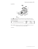
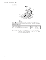
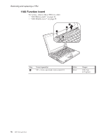
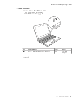
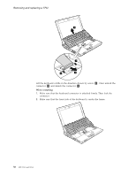
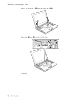
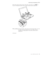
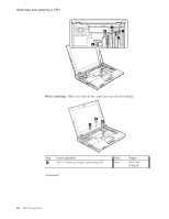
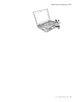
Removing and replacing a FRU 2 3 3 4 Lift the keyboard a little in the direction shown by arrow 2 . Then unlock the connector 3 and detach the connector 4 . When installing: 1. Make sure that the keyboard connector is attached firmly. Then lock the connector. 2. Make sure that the front side of the keyboard is under the frame. 58 MT 0763 and 0764
-
 1
1 -
2
-
3
-
4
-
5
-
6
-
7
-
8
-
9
-
10
-
11
-
12
-
13
-
14
-
15
-
16
-
17
-
18
-
19
-
20
-
21
-
22
-
23
-
24
-
25
-
26
-
27
-
28
-
29
-
30
-
31
-
32
-
33
-
34
-
35
-
36
-
37
-
38
-
39
-
40
-
41
-
42
-
43
-
44
-
45
-
46
-
47
-
48
-
49
-
50
-
51
-
52
-
53
-
54
-
55
-
56
-
57
-
58
-
 59
59 -
 60
60 -
 61
61 -
 62
62 -
 63
63 -
 64
64 -
 65
65 -
 66
66 -
 67
67 -
 68
68 -
 69
69 -
70
-
71
-
72
-
73
-
74
-
75
-
76
-
77
-
78
-
79
-
80
-
81
-
82
-
83
-
84
-
85
-
86
-
87
-
88
-
89
-
90
-
91
-
92
-
93
-
94
-
95
-
96
-
97
-
98
-
99
-
100
-
101
-
102
-
103
-
104
-
105
-
106
-
107
-
108
-
109
-
110
-
111
-
112
-
113
-
114
-
115
-
116
-
117
-
118
-
119
-
120
-
121
-
122
-
123
-
124
-
125
-
126
 |
 |

2
3
3
4
Lift
the
keyboard
a
little
in
the
direction
shown
by
arrow
±2²
.
Then
unlock
the
connector
±3²
and
detach
the
connector
±4²
.
When
installing:
1.
Make
sure
that
the
keyboard
connector
is
attached
firmly.
Then
lock
the
connector.
2.
Make
sure
that
the
front
side
of
the
keyboard
is
under
the
frame.
Removing
and
replacing
a
FRU
58
MT
0763
and
0764