Lenovo 2518C3U User Manual - Page 141
Accelerometer chip for the HDD Active Protection System™
 |
View all Lenovo 2518C3U manuals
Add to My Manuals
Save this manual to your list of manuals |
Page 141 highlights
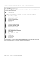
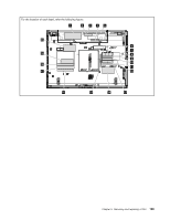
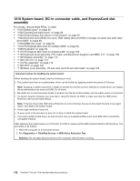
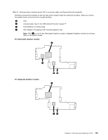
Table 31. Removal steps of system board, DC-in connector cable, and ExpressCard slot assembly Following components soldered on the top side of the system board are extremely sensitive. When you service the system board, avoid any kind of rough handling. a CPU b Accelerometer chip for the HDD Active Protection System™ c PCH (Platform Controller Hub) d GPU (Graphic Processing Unit): Discrete graphics chip Note: GPU ( d ) is only for the Switchable Graphics models. Integrated Graphics models do not have GPU on the system board. For Switchable Graphics models: a d For Integrated Graphics models: cb a cb Chapter 8. Removing and replacing a FRU 133
-
 1
1 -
2
-
3
-
4
-
5
-
6
-
7
-
8
-
9
-
10
-
11
-
12
-
13
-
14
-
15
-
16
-
17
-
18
-
19
-
20
-
21
-
22
-
23
-
24
-
25
-
26
-
27
-
28
-
29
-
30
-
31
-
32
-
33
-
34
-
35
-
36
-
37
-
38
-
39
-
40
-
41
-
42
-
43
-
44
-
45
-
46
-
47
-
48
-
49
-
50
-
51
-
52
-
53
-
54
-
55
-
56
-
57
-
58
-
59
-
60
-
61
-
62
-
63
-
64
-
65
-
66
-
67
-
68
-
69
-
70
-
71
-
72
-
73
-
74
-
75
-
76
-
77
-
78
-
79
-
80
-
81
-
82
-
83
-
84
-
85
-
86
-
87
-
88
-
89
-
90
-
91
-
92
-
93
-
94
-
95
-
96
-
97
-
98
-
99
-
100
-
101
-
102
-
103
-
104
-
105
-
106
-
107
-
108
-
109
-
110
-
111
-
112
-
113
-
114
-
115
-
116
-
117
-
118
-
119
-
120
-
121
-
122
-
123
-
124
-
125
-
126
-
127
-
128
-
129
-
130
-
131
-
132
-
133
-
134
-
135
-
 136
136 -
 137
137 -
 138
138 -
 139
139 -
 140
140 -
 141
141 -
 142
142 -
 143
143 -
 144
144 -
 145
145 -
 146
146 -
147
-
148
-
149
-
150
-
151
-
152
-
153
-
154
-
155
-
156
-
157
-
158
-
159
-
160
-
161
-
162
-
163
-
164
-
165
-
166
-
167
-
168
-
169
-
170
-
171
-
172
-
173
-
174
-
175
-
176
-
177
-
178
-
179
-
180
-
181
-
182
-
183
-
184
-
185
-
186
-
187
-
188
-
189
-
190
-
191
-
192
-
193
-
194
-
195
-
196
-
197
-
198
-
199
-
200
-
201
-
202
-
203
 |
 |
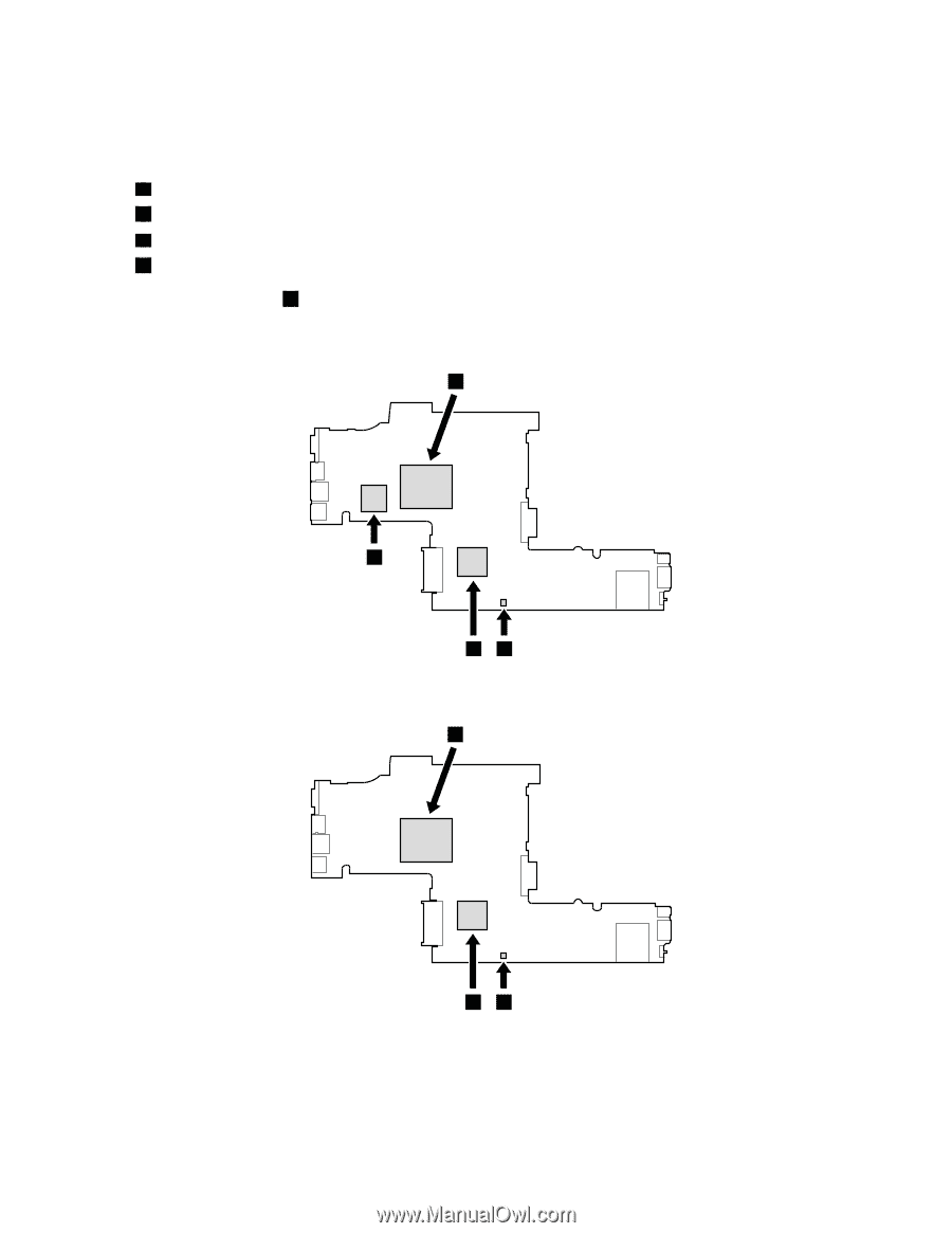
Table 31. Removal steps of system board, DC-in connector cable, and ExpressCard slot assembly
Following components soldered on the top side of the system board are extremely sensitive. When you service
the system board, avoid any kind of rough handling.
a
CPU
b
Accelerometer chip for the HDD Active Protection System™
c
PCH (Platform Controller Hub)
d
GPU (Graphic Processing Unit): Discrete graphics chip
Note:
GPU (
d
) is only for the Switchable Graphics models. Integrated Graphics models do not have
GPU on the system board.
For Switchable Graphics models:
b
c
d
a
For Integrated Graphics models:
b
c
a
Chapter 8
.
Removing and replacing a FRU
133