Lenovo A10 Laptop Hardware Maintenance Manual - Lenovo A10 - Page 46
LCD panel, LCD cable and hinges, Disconnect the connector
 |
View all Lenovo A10 Laptop manuals
Add to My Manuals
Save this manual to your list of manuals |
Page 46 highlights
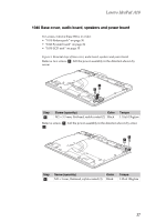
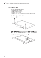
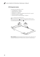
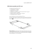
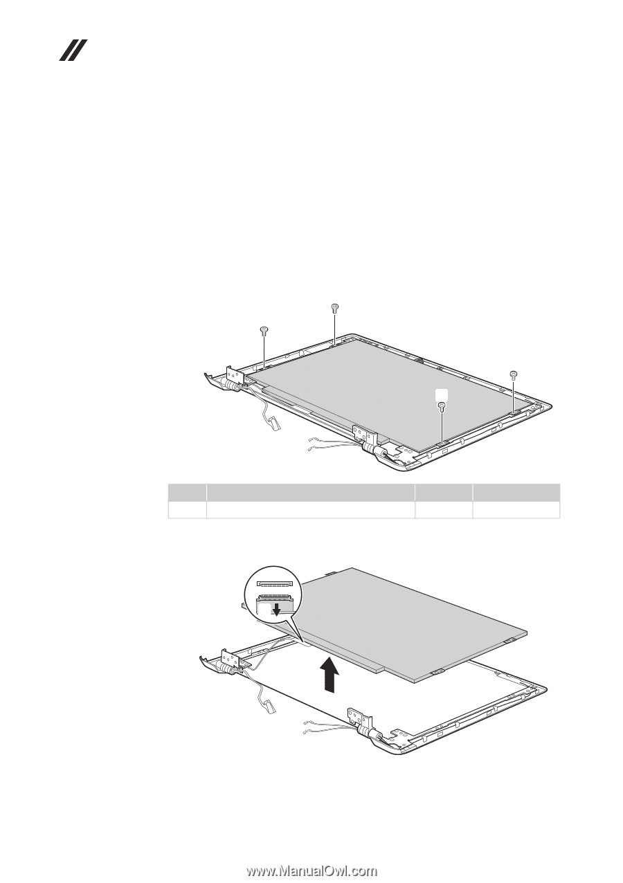
Lenovo IdeaPad A10 Hardware Maintenance Manual 1060 LCD panel, LCD cable and hinges For access, remove these FRUs in order: • "1010 Battery pack" on page 30 • "1020 System board" on page 32 • "1030 LCD unit" on page 35 • "1040 Base cover, audio board, speakers and power board" on page 37 • "1050 LCD front bezel" on page 40 Figure 6. Removal steps of LCD panel, LCD cable and hinges Remove four screws a. a a a a Step Screw (quantity) Color a M2 × 3 mm, flat-head, nylok-coated (4) Black Torque 1.35±0.15kgfcm Disconnect the connector b , lift the LCD panel in the direction shown by arrow c. b c When installing: Make sure that the connector is attached firmly. 42
-
 1
1 -
2
-
3
-
4
-
5
-
6
-
7
-
8
-
9
-
10
-
11
-
12
-
13
-
14
-
15
-
16
-
17
-
18
-
19
-
20
-
21
-
22
-
23
-
24
-
25
-
26
-
27
-
28
-
29
-
30
-
31
-
32
-
33
-
34
-
35
-
36
-
37
-
38
-
39
-
40
-
 41
41 -
 42
42 -
 43
43 -
 44
44 -
 45
45 -
 46
46 -
 47
47 -
 48
48 -
 49
49 -
 50
50 -
 51
51 -
52
-
53
-
54
-
55
-
56
-
57
-
58
-
59
-
60
-
61
-
62
-
63
-
64
-
65
-
66
 |
 |
Lenovo IdeaPad A10 Hardware Maintenance Manual
42
1060 LCD panel, LCD cable and hinges
For access, remove these FRUs in order:
•
“1010 Battery pack” on page 30
•
“1020 System board” on page 32
•
“1030 LCD unit” on page 35
•
“1040 Base cover, audio board, speakers and power board” on page 37
•
“1050 LCD front bezel” on page 40
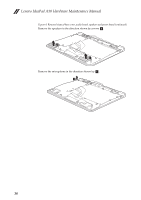
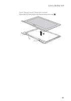
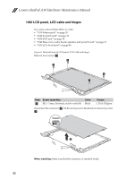
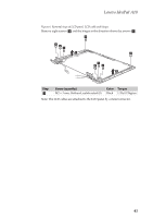
Figure 6. Removal steps of LCD panel, LCD cable and hinges
Remove four screws
.
Disconnect the connector
, lift the LCD panel in the direction shown by arrow
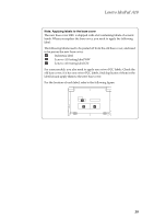
When installing:
Make sure that the connector is attached firmly.
Step
Screw (quantity)
Color
Torque
M2 × 3 mm, flat-head, nylok-coated (4)
Black
1.35±0.15kgfcm
a
a
a
a
a
a
b
c
c
b