Lenovo A530 IdeaCentre A530 All-In-One PC Hardware Maintenance Manual
Lenovo A530 Manual
 |
View all Lenovo A530 manuals
Add to My Manuals
Save this manual to your list of manuals |
Lenovo A530 manual content summary:
- Lenovo A530 | IdeaCentre A530 All-In-One PC Hardware Maintenance Manual - Page 1
IdeaCentre A530 All-In-One PC Hardware Maintenance Manual ideaideaideaCentreidea Machine Types: 10141/F0A8 [A530] - Lenovo A530 | IdeaCentre A530 All-In-One PC Hardware Maintenance Manual - Page 2
- Lenovo A530 | IdeaCentre A530 All-In-One PC Hardware Maintenance Manual - Page 3
IdeaCentre A530 All-In-One PC Hardware Maintenance Manual Machine Types: 10141/F0A8 [A530] - Lenovo A530 | IdeaCentre A530 All-In-One PC Hardware Maintenance Manual - Page 4
First Edition (June 2013)7th © Copyright Lenovo 2013. LIMITED AND RESTRICTED RIGHTS NOTICE: If data or software are delivered pursuant a General Services Administration "GSA" contract, use, reproduction, or disclosure is subject to restrictions set forth in Contract No. GS-35F-05925 - Lenovo A530 | IdeaCentre A530 All-In-One PC Hardware Maintenance Manual - Page 5
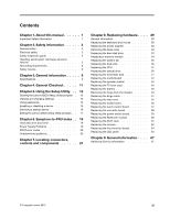
a startup device 16 Exiting the Lenovo BIOS Setup Utility program . . 17 Chapter 6. Symptom-to-FRU Index . . 19 Hard disk drive boot error 19 Power Supply Problems 19 POST error codes 20 Undetermined problems 20 Chapter 7. Locating connectors, controls and components 21 Chapter 8. Replacing - Lenovo A530 | IdeaCentre A530 All-In-One PC Hardware Maintenance Manual - Page 6
iv IdeaCentre A530 All-In-One PC Hardware Maintenance Manual - Lenovo A530 | IdeaCentre A530 All-In-One PC Hardware Maintenance Manual - Page 7
manual This manual contains service and reference information for IdeaCentre A530 All-In-One computers listed on the cover. It is intended only for trained servicers who are familiar with Lenovo computer products. Before servicing a Lenovo this manual before following any of the instructions. - Lenovo A530 | IdeaCentre A530 All-In-One PC Hardware Maintenance Manual - Page 8
2 IdeaCentre A530 All-In-One PC Hardware Maintenance Manual - Lenovo A530 | IdeaCentre A530 All-In-One PC Hardware Maintenance Manual - Page 9
be hazardous. To avoid personal injury or equipment damage, disconnect any attached power cords, telecommunication cables, network cables, and modem cables before you open the computer covers, unless instructed otherwise in the installation and configuration procedures. © Copyright Lenovo 2013 3 - Lenovo A530 | IdeaCentre A530 All-In-One PC Hardware Maintenance Manual - Page 10
instructions are Power supply units - Pumps - Blowers and fans - Motor generators and similar units. (This practice ensures correct grounding of the units.) • If an electrical accident occurs: - Use caution; do not become a victim yourself. 4 IdeaCentre A530 All-In-One PC Hardware Maintenance Manual - Lenovo A530 | IdeaCentre A530 All-In-One PC Hardware Maintenance Manual - Page 11
off power. - Send another person to get medical aid. Safety inspection guide The intent of this inspection guide is to assist you in identifying potential hazards posed by these products. Each computer, as it was designed and built, had required safety items installed to protect users and service - Lenovo A530 | IdeaCentre A530 All-In-One PC Hardware Maintenance Manual - Page 12
device covers, unless instructed otherwise in the installation and configuration procedures. • Connect and disconnect cables as described in the following table when installing, moving, or opening covers on this product or attached devices. 6 IdeaCentre A530 All-In-One PC Hardware Maintenance Manual - Lenovo A530 | IdeaCentre A530 All-In-One PC Hardware Maintenance Manual - Page 13
1. Turn everything OFF. 2. First, remove power cords from outlets. 3. Remove signal cables from connectors. 4. Remove all cables from devices. CAUTION: could result in exposure to hazardous laser radiation. There are no serviceable parts inside the device. • Use of controls or adjustments or - Lenovo A530 | IdeaCentre A530 All-In-One PC Hardware Maintenance Manual - Page 14
one power cord. To remove all electrical current from the device, ensure that all power cords are disconnected from the power source. 2 1 CAUTION: Do not place any object weighing more than 82 kg (180 lbs.) on top of rack-mounted devices. 8 IdeaCentre A530 All-In-One PC Hardware Maintenance Manual - Lenovo A530 | IdeaCentre A530 All-In-One PC Hardware Maintenance Manual - Page 15
computer models covered by this manual. Specifications This section lists the physical specifications for your computer. This section lists the physical specifications for your computer. Type IdeaCentre A530 This section lists the physical specifications. Environment Air temperature: Operating: 10 - Lenovo A530 | IdeaCentre A530 All-In-One PC Hardware Maintenance Manual - Page 16
10 IdeaCentre A530 All-In-One PC Hardware Maintenance Manual - Lenovo A530 | IdeaCentre A530 All-In-One PC Hardware Maintenance Manual - Page 17
cause of the problem: 1. Power-off the computer and all external devices. 2. Check all cables and power cords. 3. Set all display controls to the middle position. 4. Power-on all external devices. 5. Power-on the computer. • Look for displayed error codes. • Look for readable instructions or a main - Lenovo A530 | IdeaCentre A530 All-In-One PC Hardware Maintenance Manual - Page 18
12 IdeaCentre A530 All-In-One PC Hardware Maintenance Manual - Lenovo A530 | IdeaCentre A530 All-In-One PC Hardware Maintenance Manual - Page 19
then turn on the computer. When the Lenovo BIOS Setup Utility program is displayed, release the F1 key. Note: If a Power-On Password or an Administrator Password has been and a mix of letters and numbers. • Do not use your name or your user name. • Do not use a common word or a common name. • Use - Lenovo A530 | IdeaCentre A530 All-In-One PC Hardware Maintenance Manual - Page 20
Enter key. A Setup Notice will be displayed confirming that your changes have been saved. 5. Return to the Lenovo BIOS Setup Utility program menu and select the Exit option. 6. Select Save Changes and Exit from the menu. Power-On Password 14 IdeaCentre A530 All-In-One PC Hardware Maintenance Manual - Lenovo A530 | IdeaCentre A530 All-In-One PC Hardware Maintenance Manual - Page 21
Power-On Password, do the following: 1. Start the Lenovo BIOS Setup Utility program (see "Starting the Lenovo Devices options is used to enable or disable user access to the following: USB Functions Select whether connected to the SATA connectors (e.g. hard disk drives or the optical disk drive) - Lenovo A530 | IdeaCentre A530 All-In-One PC Hardware Maintenance Manual - Page 22
connected to the audio connectors (e.g. headphones or a Support or LAN Boot Agent. 4. Select Disabled or Enabled and press the Enter key. 5. Return to the Lenovo Device driver support is required for AHCI. Depending on how the hard disk IdeaCentre A530 All-In-One PC Hardware Maintenance Manual - Lenovo A530 | IdeaCentre A530 All-In-One PC Hardware Maintenance Manual - Page 23
press the Esc key several times. Do one of the following: • If you want to save the new settings, select Save Changes and Exit from the menu. When the Save & reset window shows, select the Yes button, and then press the Enter key to exit the Lenovo BIOS Setup Utility program. • If you do - Lenovo A530 | IdeaCentre A530 All-In-One PC Hardware Maintenance Manual - Page 24
18 IdeaCentre A530 All-In-One PC Hardware Maintenance Manual - Lenovo A530 | IdeaCentre A530 All-In-One PC Hardware Maintenance Manual - Page 25
drive. Replace the hard disk drive. Power Supply Problems Follow these procedures if you suspect there is a power supply problem. Check/Verify Check that the following are properly installed: • Power Cord • On/Off Switch connector • System Board Power Supply connectors • Microprocessor connections - Lenovo A530 | IdeaCentre A530 All-In-One PC Hardware Maintenance Manual - Page 26
video RAM e. Hard disk drive f. Disk drive 3. Power-on the computer to re-test the system. 4. Repeat steps 1 through 3 until you find the failing device or component. If all devices and components have been removed and the problem continues, replace the system board. 20 IdeaCentre A530 All-In-One - Lenovo A530 | IdeaCentre A530 All-In-One PC Hardware Maintenance Manual - Page 27
provides illustrations to help locate the various connectors, controls and components of the computer. 3. Built-in microphone (selected models only) 4. Power indicator 5. Hard disk drive indicator 6. Bluetooth status indicator 7. Wi-Fi status indicator 8. HDMI-in indicator 9. Monitor On/Off 17 16 9 - Lenovo A530 | IdeaCentre A530 All-In-One PC Hardware Maintenance Manual - Page 28
right side of the computer. 8 7 1 2 34 1. Air vents 2. USB 3.0 connector 3. HDMI-in connector (selected models only) 4. HDMI-out connector 5 6 5. Optical drive eject button 6. Optical drive 7. Power button 8. Anti-scratch protector 22 IdeaCentre A530 All-In-One PC Hardware Maintenance Manual - Lenovo A530 | IdeaCentre A530 All-In-One PC Hardware Maintenance Manual - Page 29
and components on the rear of the computer. 123 4 1. TV-Tuner connector (selected models only) 2. Headphone connector 3. Microphone connector 4. USB 3.0 connector 5 6 78 5. USB 2.0 connectors (2) 6. Power connector 7. Ethernet connector (RJ45) 8. Security cable slot Chapter 7. Locating - Lenovo A530 | IdeaCentre A530 All-In-One PC Hardware Maintenance Manual - Page 30
Power switch board 18. Front function board 19. Battery 20. Solid state disk 21. TV-Tuner card 22. Glass 23. Panel frame 24. LED panel 25. Middle frame 26. Rear cover 27. Rear cover deco 28. Touch control board 29. Converter 30. Heat-sink 24 IdeaCentre A530 All-In-One PC Hardware Maintenance Manual - Lenovo A530 | IdeaCentre A530 All-In-One PC Hardware Maintenance Manual - Page 31
supports a variety of devices that are factory-installed or that can be installed later. The following illustration shows the location of connectors and components on the front of the motherboard. 1. HDMI-out connector 2. HDMI-in connector 3. USB 3.0 connector 4. Ethernet connector(RJ45) 5. Power - Lenovo A530 | IdeaCentre A530 All-In-One PC Hardware Maintenance Manual - Page 32
The following illustration shows the location of connectors and components on the back of the motherboard. 22 23 22. TV-Tuner card connector 23. Battery 26 IdeaCentre A530 All-In-One PC Hardware Maintenance Manual - Lenovo A530 | IdeaCentre A530 All-In-One PC Hardware Maintenance Manual - Page 33
components and controls on the back of LED panel. 1 2 3 8 7 6 1. Bluetooth module 2. Wi-Fi card 3. Camera 4. Front function board 5 4 5. Scalar board 6. Converter board 7. Touch control board 8. Power switch board Chapter 7. Locating connectors, controls and components 27 - Lenovo A530 | IdeaCentre A530 All-In-One PC Hardware Maintenance Manual - Page 34
28 IdeaCentre A530 All-In-One PC Hardware Maintenance Manual - Lenovo A530 | IdeaCentre A530 All-In-One PC Hardware Maintenance Manual - Page 35
the Safety and Warranty Guide, go to the Support Web site at: http://support.lenovo.com. Note: Use only parts provided by Lenovo. General information Pre-disassembly instructions Before starting the disassembly procedure, make sure that you do the following: 1. Turn off the power to the system and - Lenovo A530 | IdeaCentre A530 All-In-One PC Hardware Maintenance Manual - Page 36
, CDs, DVDs, or memory cards) from the drives, shut down the operating system, and turn off the computer and all attached devices. Step 2. Locate the connector for the power cord. Refer to "Rear view". 30 IdeaCentre A530 All-In-One PC Hardware Maintenance Manual - Lenovo A530 | IdeaCentre A530 All-In-One PC Hardware Maintenance Manual - Page 37
Step 3. Disconnect the failing power adapter from the computer. Step 4. To install the new power adapter: a. Connect the new power adapter to the same connector. Chapter 8. Replacing hardware 31 - Lenovo A530 | IdeaCentre A530 All-In-One PC Hardware Maintenance Manual - Page 38
connectors. Place the computer face-down on a soft flat surface, then remove the 7 screws that secure the base cover to the base. Step 5. Return the computer to an upright position, then lift up the base cover and slide it out as shown. 32 IdeaCentre A530 All-In-One PC Hardware Maintenance Manual - Lenovo A530 | IdeaCentre A530 All-In-One PC Hardware Maintenance Manual - Page 39
"Rear view" for help with locating the various connectors. Remove the base cover. Refer to "Removing the base cover". Remove the 2 screws that secure the hard disk drive to the motherboard. 1 Disconnect the data and power cables from the hard disk drive. 2 2 1 1 Chapter 8. Replacing hardware 33 - Lenovo A530 | IdeaCentre A530 All-In-One PC Hardware Maintenance Manual - Page 40
. This includes power cords, input/output (I/O) cables, and any other cables that are connected to the computer. Refer to "Left and right view" and "Rear view" for help with locating the various connectors. Remove the base cover. Refer to "Removing the base cover". 34 IdeaCentre A530 All-In-One PC - Lenovo A530 | IdeaCentre A530 All-In-One PC Hardware Maintenance Manual - Page 41
. Disconnect all cables attached to the computer. This includes power cords, input/output (I/O) cables, and any other cables that are connected to the computer. Refer to "Left and right view" and "Rear view" for help with locating the various connectors. Remove the base cover. Refer to "Removing the - Lenovo A530 | IdeaCentre A530 All-In-One PC Hardware Maintenance Manual - Page 42
the 3 screws. c. Connect the new power cable to the connector on motherboard. Step 9. Reattach the base connectors. Remove the base cover. Refer to "Removing the base cover". Remove the system fan. Refer to "Replacing the system fan". 36 IdeaCentre A530 All-In-One PC Hardware Maintenance Manual - Lenovo A530 | IdeaCentre A530 All-In-One PC Hardware Maintenance Manual - Page 43
. Disconnect all cables attached to the computer. This includes power cords, input/output (I/O) cables, and any other cables that are connected to the computer. Refer to "Left and right view" and "Rear view" for help with locating the various connectors. Remove the base cover. Refer to "Removing the - Lenovo A530 | IdeaCentre A530 All-In-One PC Hardware Maintenance Manual - Page 44
the tabs in the microprocessor socket. Important: To avoid damaging the microprocessor contacts, keep the microprocessor completely level while installing it into the socket. 38 IdeaCentre A530 All-In-One PC Hardware Maintenance Manual - Lenovo A530 | IdeaCentre A530 All-In-One PC Hardware Maintenance Manual - Page 45
. Disconnect all cables attached to the computer. This includes power cords, input/output (I/O) cables, and any other cables that are connected to the computer. Refer to "Left and right view" and "Rear view" for help with locating the various connectors. Remove the base cover. Refer to "Removing the - Lenovo A530 | IdeaCentre A530 All-In-One PC Hardware Maintenance Manual - Page 46
and lift the optical drive up to remove it. Step 7. Remove the 4 screws that secure the optical drive to the bracket and disconnect the data connector from the rear of optical drive. 40 IdeaCentre A530 All-In-One PC Hardware Maintenance Manual - Lenovo A530 | IdeaCentre A530 All-In-One PC Hardware Maintenance Manual - Page 47
. Disconnect all cables attached to the computer. This includes power cords, input/output (I/O) cables, and any other cables that are connected to the computer. Refer to "Left and right view" and "Rear view" for help with locating the various connectors. Remove the base cover. Refer to "Removing the - Lenovo A530 | IdeaCentre A530 All-In-One PC Hardware Maintenance Manual - Page 48
help with locating the various connectors. Step 4. Remove the base cover. Refer to "Removing the base cover". Step 5. Remove the hard disk drive. Refer to "Replacing the hard disk drive". Step 6. Remove from the chassis and put them aside. 42 IdeaCentre A530 All-In-One PC Hardware Maintenance Manual - Lenovo A530 | IdeaCentre A530 All-In-One PC Hardware Maintenance Manual - Page 49
Step 14. Remove the 7 screws that secure the motherboard to the chassis and slide it out as shown. Step 15. Remove the 2 screws that secure the TV-Tuner card to the motherboard. Step 16. Disconnect the antenna cable(s) from the TV-Tuner card. Step 17. Pull the TV-Tuner card upward to remove it from - Lenovo A530 | IdeaCentre A530 All-In-One PC Hardware Maintenance Manual - Page 50
the solid state disk, optical drive, CPU, heat-sink, system fan, memory module, and hard disk drive to the new motherboard. g. Connect all the cables to the new motherboard. Step 20. Reattach the base cover and secure it with the screws. 44 IdeaCentre A530 All-In-One PC Hardware Maintenance Manual - Lenovo A530 | IdeaCentre A530 All-In-One PC Hardware Maintenance Manual - Page 51
2. Unplug all power cords from electrical outlets. Step 3. Disconnect all cables attached to the computer. This includes power cords, input/ various connectors. Step 4. Remove the base cover. Refer to "Removing the base cover". Step 5. Remove the hard disk drive. Refer to "Replacing the hard disk - Lenovo A530 | IdeaCentre A530 All-In-One PC Hardware Maintenance Manual - Page 52
cable to the connector on the motherboard. Step 14. Reattach the optical drive, heat-sink, system fan, and hard disk drive to power cords from electrical outlets. Step 3. Disconnect all cables attached to the computer. This includes power IdeaCentre A530 All-In-One PC Hardware Maintenance Manual - Lenovo A530 | IdeaCentre A530 All-In-One PC Hardware Maintenance Manual - Page 53
the chassis and secure the motherboard to the chassis with the 7 screws. Step 17. Reattach the speaker system, optical drive, heat-sink, system fan, and hard disk drive to the motherboard. Step 18. Reconnect all the cables to the motherboard. Step 19. Reattach the base cover and secure it with the - Lenovo A530 | IdeaCentre A530 All-In-One PC Hardware Maintenance Manual - Page 54
help with locating the various connectors. Step 4. Remove the base cover. Refer to "Removing the base cover". Step 5. Remove the hard disk drive. Refer to "Replacing the hard disk drive". Step 6. Remove chassis and slide it out as shown. 48 IdeaCentre A530 All-In-One PC Hardware Maintenance Manual - Lenovo A530 | IdeaCentre A530 All-In-One PC Hardware Maintenance Manual - Page 55
screws. Step 15. Reattach the speaker system, optical drive, heat-sink, system fan, and hard disk drive to the motherboard. Step 16. Reconnect all the cables to the motherboard. Step 17 and all attached devices. Step 2. Unplug all power cords from electrical outlets. Chapter 8. Replacing hardware 49 - Lenovo A530 | IdeaCentre A530 All-In-One PC Hardware Maintenance Manual - Page 56
and slide the hinge into position. b. Secure the hinge to the chassis with the 6 screws. c. Reconnect the scalar headphone input, scalar and DVI/HDMI cables to the motherboard. Step 8. Reattach the base cover and secure it with the screws. 50 IdeaCentre A530 All-In-One PC Hardware Maintenance Manual - Lenovo A530 | IdeaCentre A530 All-In-One PC Hardware Maintenance Manual - Page 57
. Disconnect all cables attached to the computer. This includes power cords, input/output (I/O) cables, and any other cables that are connected to the computer. Refer to "Left and right view" and "Rear view" for help with locating the various connectors. Remove the base cover. Refer to "Removing the - Lenovo A530 | IdeaCentre A530 All-In-One PC Hardware Maintenance Manual - Page 58
is pinned into place, use short, sharp movements to prise it up. 2 2 Step 10. Press down the hinge and slide out the rear cover. 52 IdeaCentre A530 All-In-One PC Hardware Maintenance Manual - Lenovo A530 | IdeaCentre A530 All-In-One PC Hardware Maintenance Manual - Page 59
Step 11. Disconnect the scalar 10 and HDMI/DVI 11 cables from the connectors on the scalar board. LED/CIR LVDS MMB P owe r Blue tooth WLAN Ca me ra Conve rte r Touch control S ca la r HDMI/DVI Step 12. Remove the 5 screws that secure the hinge to the middle frame and set the hinge - Lenovo A530 | IdeaCentre A530 All-In-One PC Hardware Maintenance Manual - Page 60
Remove the 4 screws that secure the hinge front cover to the hinge. 2 Step 15. Use a flat head screw driver to prise the front cover off gently, and then detach the hinge cable from the front cover. 1 1 2 and secure it with the 5 screws. 54 IdeaCentre A530 All-In-One PC Hardware Maintenance Manual - Lenovo A530 | IdeaCentre A530 All-In-One PC Hardware Maintenance Manual - Page 61
screws. j. Connect the new scalar headphone input, scalar and DVI/HDMI cables to the connectors on the motherboard. Step 17. Reattach the base cover and secure . Unplug all power cords from electrical outlets. Disconnect all cables attached to the computer. This includes power cords, input/output - Lenovo A530 | IdeaCentre A530 All-In-One PC Hardware Maintenance Manual - Page 62
and DVI/HDMI cables to connectors. Remove the base cover. Refer to "Removing the base cover". Remove the hinge from the chassis. Refer to "Removing the hinge from the chassis". Remove the rear cover. Refer to "Removing the rear cover". 56 IdeaCentre A530 All-In-One PC Hardware Maintenance Manual - Lenovo A530 | IdeaCentre A530 All-In-One PC Hardware Maintenance Manual - Page 63
and reconnect the scalar headphone input, scalar and DVI/HDMI cables to the motherboard. Step 12. Reattach the power cords, input/output (I/O) cables, and any other cables that are connected to the computer. Refer to "Left and right view" and "Rear view" for help with locating the various connectors - Lenovo A530 | IdeaCentre A530 All-In-One PC Hardware Maintenance Manual - Page 64
the scalar headphone input, scalar and DVI/HDMI cables to the motherboard. Step 12. connectors. Remove the base cover. Refer to "Removing the base cover". Remove the hinge from the chassis. Refer to "Removing the hinge from the chassis". 58 IdeaCentre A530 All-In-One PC Hardware Maintenance Manual - Lenovo A530 | IdeaCentre A530 All-In-One PC Hardware Maintenance Manual - Page 65
12. Reattach the hinge to the chassis, and reconnect the scalar headphone input, scalar and DVI/HDMI cables to the motherboard. Step 13. Reattach the base cover and secure it with the screws. Replacing the power switch board Note: Turn off the computer and wait 3 to 5 minutes to let it cool down - Lenovo A530 | IdeaCentre A530 All-In-One PC Hardware Maintenance Manual - Page 66
the scalar headphone input, scalar and DVI/HDMI cables to the motherboard. Step 12. connectors. Remove the base cover. Refer to "Removing the base cover". Remove the hinge from the chassis. Refer to "Removing the hinge from the chassis". 60 IdeaCentre A530 All-In-One PC Hardware Maintenance Manual - Lenovo A530 | IdeaCentre A530 All-In-One PC Hardware Maintenance Manual - Page 67
and reconnect the scalar headphone input, scalar and DVI/HDMI cables to the motherboard. Step 12. Reattach the power cords, input/output (I/O) cables, and any other cables that are connected to the computer. Refer to "Left and right view" and "Rear view" for help with locating the various connectors - Lenovo A530 | IdeaCentre A530 All-In-One PC Hardware Maintenance Manual - Page 68
and DVI/HDMI cables to connectors. Remove the base cover. Refer to "Removing the base cover". Remove the hinge from the chassis. Refer to "Removing the hinge from the chassis". Remove the rear cover. Refer to "Removing the rear cover". 62 IdeaCentre A530 All-In-One PC Hardware Maintenance Manual - Lenovo A530 | IdeaCentre A530 All-In-One PC Hardware Maintenance Manual - Page 69
. Reconnect the scalar headphone input, scalar and DVI/HDMI cables to the motherboard. Step 13. Reattach the power cords, input/output (I/O) cables, and any other cables that are connected to the computer. Refer to "Left and right view" and "Rear view" for help with locating the various connectors - Lenovo A530 | IdeaCentre A530 All-In-One PC Hardware Maintenance Manual - Page 70
HDMI Lenovo power cords, input/output (I/O) cables, and any other cables that are connected to the computer. Refer to "Left and right view" and "Rear view" for help with locating the various connectors. Remove the base cover. Refer to "Removing the base cover". 64 IdeaCentre A530 All-In-One - Lenovo A530 | IdeaCentre A530 All-In-One PC Hardware Maintenance Manual - Page 71
the touch control board". Step 9. Remove the converter board. Refer to "Replacing the converter board ". Step 10. Remove the power switch board. Refer to "Replacing the power switch board". Step 11. Remove the Bluetooth module. Refer to "Replacing the Bluetooth module". Step 12. Remove the Wi-Fi - Lenovo A530 | IdeaCentre A530 All-In-One PC Hardware Maintenance Manual - Page 72
and front bezel. c. Attach the Wi-Fi card, Bluetooth module, power switch board, converter board, touch control board, scalar board and front HDMI cables to the motherboard. Step 22. Reattach the base cover and secure it with the screws. 66 IdeaCentre A530 All-In-One PC Hardware Maintenance Manual - Lenovo A530 | IdeaCentre A530 All-In-One PC Hardware Maintenance Manual - Page 73
by this manual. Additional Service Information This chapter provides additional information that the service representative might find helpful. Power management Power management reduces the power consumption of certain components of the computer such as the system power supply, processor, hard disk
-
 1
1 -
 2
2 -
 3
3 -
 4
4 -
 5
5 -
 6
6 -
 7
7 -
8
-
9
-
10
-
11
-
12
-
13
-
14
-
15
-
16
-
17
-
18
-
19
-
20
-
21
-
22
-
23
-
24
-
25
-
26
-
27
-
28
-
29
-
30
-
31
-
32
-
33
-
34
-
35
-
36
-
37
-
38
-
39
-
40
-
41
-
42
-
43
-
44
-
45
-
46
-
47
-
48
-
49
-
50
-
51
-
52
-
53
-
54
-
55
-
56
-
57
-
58
-
59
-
60
-
61
-
62
-
63
-
64
-
65
-
66
-
67
-
68
-
69
-
70
-
71
-
72
-
73
 |
 |

IdeaCentre A530 All-In-One PC
Hardware Maintenance Manual
Machine Types: 10141/F0A8 [A530]