Lenovo B40-70 Hardware Maintenance Manual - Lenovo B40-xx Notebook - Page 56
LCD unit and base cover
 |
View all Lenovo B40-70 manuals
Add to My Manuals
Save this manual to your list of manuals |
Page 56 highlights
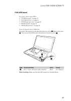
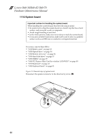
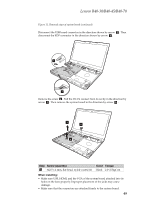
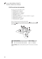
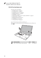
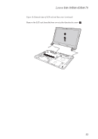
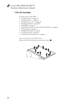
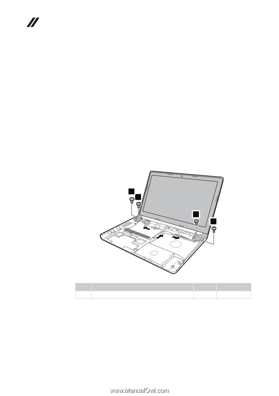
Lenovo B40-30/B40-45/ B40-70 Hardware Maintenance Manual 1140 LCD unit and base cover For access, remove these FRUs: • "1010 Battery pack" on page 33 • "1020 Optical drive" on page 34 • "1030 Bottom slot cover" on page 36 • "1040 Hard disk drive" on page 37 • "1050 DIMM" on page 39 • "1060 PCI Express Mini Card for wireless LAN/WAN" on page 40 • "1070 Keyboard" on page 41 • "1080 Keyboard bezel" on page 43 • "1100 USB board" on page 47 • "1110 System board" on page 48 Figure 14. Removal steps of LCD unit and base cover Release the two antenna cables from the cable guides by arrows. Remove six screws a b. 1 1 1 1 Step Screw (quantity) a b M2.5 x 4 mm, flat‐head, nylok‐coated (6) Color Black Torque 2.0~2.5kgf.cm 52
-
 1
1 -
2
-
3
-
4
-
5
-
6
-
7
-
8
-
9
-
10
-
11
-
12
-
13
-
14
-
15
-
16
-
17
-
18
-
19
-
20
-
21
-
22
-
23
-
24
-
25
-
26
-
27
-
28
-
29
-
30
-
31
-
32
-
33
-
34
-
35
-
36
-
37
-
38
-
39
-
40
-
41
-
42
-
43
-
44
-
45
-
46
-
47
-
48
-
49
-
50
-
 51
51 -
 52
52 -
 53
53 -
 54
54 -
 55
55 -
 56
56 -
 57
57 -
 58
58 -
 59
59 -
 60
60 -
 61
61 -
62
-
63
-
64
-
65
-
66
-
67
-
68
-
69
-
70
-
71
-
72
-
73
-
74
-
75
-
76
-
77
-
78
-
79
-
80
-
81
-
82
-
83
-
84
-
85
 |
 |
Lenovo B40-30/B40-45/ B40-70
Hardware Maintenance Manual
52
1140 LCD unit and base cover
For
access,
remove
these
FRUs:
•
“1010
Battery
pack”
on
page
33
•
“1020
Optical
drive”
on
page
34
•
“1030
Bottom
slot
cover”
on
page
36
•
“1040
Hard
disk
drive”
on
page
37
•
“1050
DIMM”
on
page
39
•
“1060
PCI
Express
Mini
Card
for
wireless
LAN/WAN”
on
page
40
•
“1070
Keyboard”
on
page
41
•
“1080
Keyboard
bezel”
on
page
43
•
“1100
USB
board”
on
page
47
•
“1110
System
board”
on
page
48
Figure
14.
Removal
steps
of
LCD
unit
and
base
cover
Release
the
two
antenna
cables
from
the
cable
guides
by
arrows.
Remove
six
screws
Step
Screw (quantity)
Color
Torque
M2.5
x
4
mm,
flat
‐
head,
nylok
‐
coated
(6)
Black
2.0~2.5kgf.cm
a
1
1
1
1
a