Lenovo C240 Hardware Maintenance Manual - Page 35
Separate the cover from the defective optical drive.
 |
View all Lenovo C240 manuals
Add to My Manuals
Save this manual to your list of manuals |
Page 35 highlights
Step 4. Push a small iron stick (paper clip) into the small hole on the optical drive cover so that the disk springs out as shown. 1 Step 5. Remove the screw that secures the optical drive to the chassis. 2 Step 6. Slide out the optical drive as shown. 3 Step 7. Use a small flat head screwdriver to press and push out the pins that secure the cover to the disk. 4 5 Step 8. Separate the cover from the defective optical drive. Step 9. Install the new optical drive as follows: Chapter 8. Replacing hardware 29
-
 1
1 -
2
-
3
-
4
-
5
-
6
-
7
-
8
-
9
-
10
-
11
-
12
-
13
-
14
-
15
-
16
-
17
-
18
-
19
-
20
-
21
-
22
-
23
-
24
-
25
-
26
-
27
-
28
-
29
-
 30
30 -
 31
31 -
 32
32 -
 33
33 -
 34
34 -
 35
35 -
 36
36 -
 37
37 -
 38
38 -
 39
39 -
 40
40 -
41
-
42
-
43
-
44
-
45
-
46
-
47
-
48
-
49
-
50
-
51
-
52
-
53
-
54
-
55
 |
 |
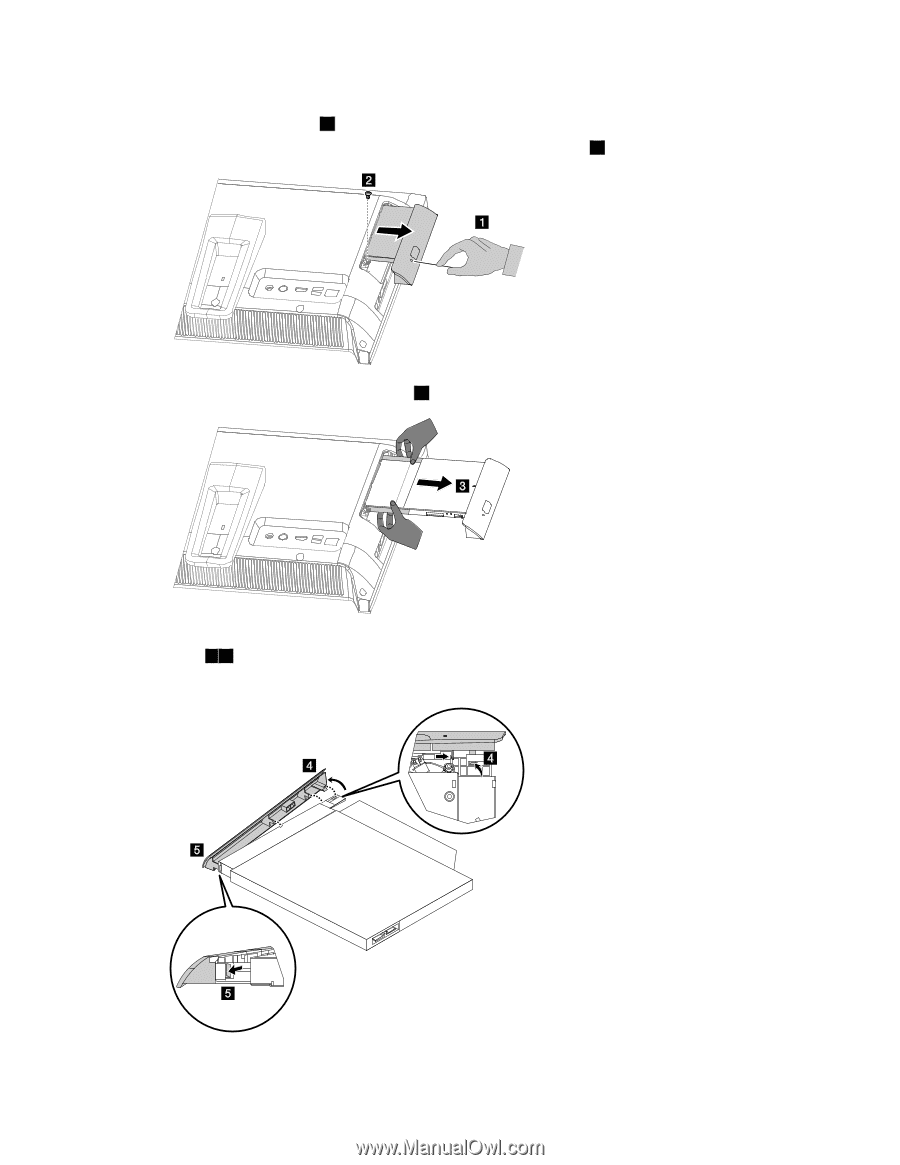
Step 4.
Push a small iron stick (paper clip) into the small hole on the optical drive cover so that the disk
springs out as shown.
1
Step 5.
Remove the screw that secures the optical drive to the chassis.
2
Step 6.
Slide out the optical drive as shown.
3
Step 7.
Use a small flat head screwdriver to press and push out the pins that secure the cover to the
disk.
4
5
Step 8.
Separate the cover from the defective optical drive.
Step 9.
Install the new optical drive as follows:
Chapter 8
.
Replacing hardware
29