Lenovo C355 Lenovo C355/C455 All-In-One Computer Hardware Maintenance Manual - Page 28
Left and right view, Attention, Do not insert 3-inch discs into the optical drive.
 |
View all Lenovo C355 manuals
Add to My Manuals
Save this manual to your list of manuals |
Page 28 highlights
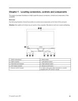
Left and right view The following illustration shows the location of connectors, controls and components on the left and right side of the computer. 7 8 1 2 3 4 5 6 1. USB connector 2. Headphone connector 3. Microphone connector 4. USB connector 5. Memory card reader 6. Power button 7. Optical drive eject button 8. Optical drive Attention: Do not insert 3-inch discs into the optical drive. 22 Lenovo C355/C455 All-In-One ComputerHardware Maintenance Manual
-
 1
1 -
2
-
3
-
4
-
5
-
6
-
7
-
8
-
9
-
10
-
11
-
12
-
13
-
14
-
15
-
16
-
17
-
18
-
19
-
20
-
21
-
22
-
 23
23 -
 24
24 -
 25
25 -
 26
26 -
 27
27 -
 28
28 -
 29
29 -
 30
30 -
 31
31 -
 32
32 -
 33
33 -
34
-
35
-
36
-
37
-
38
-
39
-
40
-
41
-
42
-
43
-
44
-
45
-
46
-
47
-
48
-
49
-
50
-
51
-
52
-
53
-
54
-
55
-
56
-
57
-
58
-
59
-
60
-
61
-
62
-
63
-
64
-
65
-
66
-
67
-
68
-
69
-
70
-
71
-
72
-
73
-
74
-
75
-
76
-
77
-
78
-
79
-
80
-
81
-
82
-
83
 |
 |

Left and right view
The following illustration shows the location of connectors, controls and components on the left and right
side of the computer.
1. USB connector
5. Memory card reader
2. Headphone connector
6. Power button
3. Microphone connector
7. Optical drive eject button
4. USB connector
8. Optical drive
Attention:
Do not insert 3-inch discs into the optical drive.
22
Lenovo C355/C455 All-In-One ComputerHardware Maintenance Manual