Lenovo C355 Lenovo C355/C455 All-In-One Computer Hardware Maintenance Manual - Page 29
The following illustration shows the location of connectors and components on the rear of the computer.
 |
View all Lenovo C355 manuals
Add to My Manuals
Save this manual to your list of manuals |
Page 29 highlights
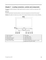
Rear view The following illustration shows the location of connectors and components on the rear of the computer. 9 8 1 2 3 4 56 7 1. TV tuner connector (selected models only, 2 connectors 6. USB connector for Japan) 2. TV tuner connector (selected models only, 2 connectors 7. HDMI-out connector (selected models only) for Japan) 3. Power connector 8. Security cable slot 4. Ethernet connector 9. Air vents 5. USB connector Chapter 7. Locating connectors, controls and components 23
-
 1
1 -
2
-
3
-
4
-
5
-
6
-
7
-
8
-
9
-
10
-
11
-
12
-
13
-
14
-
15
-
16
-
17
-
18
-
19
-
20
-
21
-
22
-
23
-
 24
24 -
 25
25 -
 26
26 -
 27
27 -
 28
28 -
 29
29 -
 30
30 -
 31
31 -
 32
32 -
 33
33 -
 34
34 -
35
-
36
-
37
-
38
-
39
-
40
-
41
-
42
-
43
-
44
-
45
-
46
-
47
-
48
-
49
-
50
-
51
-
52
-
53
-
54
-
55
-
56
-
57
-
58
-
59
-
60
-
61
-
62
-
63
-
64
-
65
-
66
-
67
-
68
-
69
-
70
-
71
-
72
-
73
-
74
-
75
-
76
-
77
-
78
-
79
-
80
-
81
-
82
-
83
 |
 |

Rear view
The following illustration shows the location of connectors and components on the rear of the computer.
1. TV tuner connector (selected models only, 2 connectors
for Japan)
6. USB connector
2. TV tuner connector (selected models only, 2 connectors
for Japan)
7. HDMI-out connector (selected models only)
3. Power connector
8. Security cable slot
4. Ethernet connector
9. Air vents
5. USB connector
Chapter 7
.
Locating connectors, controls and components
23