Lenovo H520 Lenovo H520s Hardware Maintenance Manual - Page 36
Replacing an optical drive, To remove the front bezel
 |
View all Lenovo H520 manuals
Add to My Manuals
Save this manual to your list of manuals |
Page 36 highlights
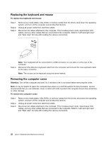
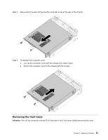
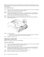
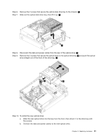
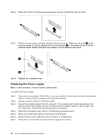
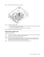
Note: It may be helpful to place the computer face-down on a soft flat surface for this procedure. Lenovo recommends that you use a blanket, towel, or other soft cloth to protect the computer screen from scratches or other damage. To remove the front bezel: Step 1. Step 2. Step 3. Step 4. Step 5. Remove any media (disks, CDs, DVDs, or memory cards) from the drives, shut down the operating system, and turn off the computer and all attached devices. Unplug all power cords from electrical outlets. Disconnect all cables attached to the computer. This includes power cords, input/output (I/O) cables, and any other cables that are connected to the computer. Refer to "Left and right view" and "Rear view" for help with locating the various connectors. Remove the computer cover. Refer to "Removing the computer cover". Remove the front bezel by releasing the three plastic tabs inside the chassis and pushing the bezel outward as shown. Step 6. To reattach the bezel: a. Align the plastic tabs on the bottom of the bezel with the corresponding holes in the chassis, and then snap it into position at the bottom and top of the chassis. Step 7. Reattach the computer cover. Replacing an optical drive Note: For this procedure, it helps to lay the computer flat. To replace an optical drive: Step 1. Step 2. Step 3. Step 4. Step 5. Remove any media (disks, CDs, DVDs, or memory cards) from the drives, shut down the operating system, and turn off the computer and all attached devices. Unplug all power cords from electrical outlets. Disconnect all cables attached to the computer. This includes power cords, input/output (I/O) cables, and any other cables that are connected to the computer. Refer to "Left and right view" and "Rear view" for help with locating the various connectors. Remove the computer cover. Refer to "Removing the computer cover". Remove the front bezel. Refer to "Removing the front bezel". 30 Lenovo H520sHardware Maintenance Manual
-
 1
1 -
2
-
3
-
4
-
5
-
6
-
7
-
8
-
9
-
10
-
11
-
12
-
13
-
14
-
15
-
16
-
17
-
18
-
19
-
20
-
21
-
22
-
23
-
24
-
25
-
26
-
27
-
28
-
29
-
30
-
 31
31 -
 32
32 -
 33
33 -
 34
34 -
 35
35 -
 36
36 -
 37
37 -
 38
38 -
 39
39 -
 40
40 -
 41
41 -
42
-
43
-
44
-
45
-
46
-
47
-
48
-
49
-
50
-
51
-
52
-
53
-
54
-
55
-
56
-
57
-
58
-
59
 |
 |
