Lenovo Horizon 2e Table PC Lenovo HORIZON 2e All-In-One PC Hardware Maintenanc - Page 49
Connect the converter cables to the connectors on both LED panel.
 |
View all Lenovo Horizon 2e Table PC manuals
Add to My Manuals
Save this manual to your list of manuals |
Page 49 highlights
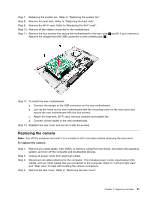
Step 9. The LED panel module including: LED panelGlassLED bracketsTouch control boardNFC board Step 10. To install the new the LED panel module: a. Connect the LVDS cable to the connector and touch control board. b. Reattach the camera to the front bezel. c. Connect the converter cables to the connectors on both LED panel. d. Connect the LVDS cable to the connectors on both LED panel. e. Connect the touch cable to the connectors on the touch control board. Step 11. Reattach the rear cover and secure it with the screws. Chapter 8. Replacing hardware 43
-
 1
1 -
2
-
3
-
4
-
5
-
6
-
7
-
8
-
9
-
10
-
11
-
12
-
13
-
14
-
15
-
16
-
17
-
18
-
19
-
20
-
21
-
22
-
23
-
24
-
25
-
26
-
27
-
28
-
29
-
30
-
31
-
32
-
33
-
34
-
35
-
36
-
37
-
38
-
39
-
40
-
41
-
42
-
43
-
 44
44 -
 45
45 -
 46
46 -
 47
47 -
 48
48 -
 49
49 -
 50
50 -
 51
51 -
 52
52 -
 53
53 -
 54
54 -
55
 |
 |

Step 9.
The LED panel module including: LED panelGlassLED bracketsTouch control boardNFC board
Step 10. To install the new the LED panel module:
a.
Connect the LVDS cable to the connector and touch control board.
b.
Reattach the camera to the front bezel.
c.
Connect the converter cables to the connectors on both LED panel.
d.
Connect the LVDS cable to the connectors on both LED panel.
e.
Connect the touch cable to the connectors on the touch control board.
Step 11. Reattach the rear cover and secure it with the screws.
Chapter 8
.
Replacing hardware
43