Lenovo IdeaPad S100c IdeaPad S100c Hardware Maintenance Manual First Edition ( - Page 65
LCD panel, LCD cable and hinges
 |
View all Lenovo IdeaPad S100c manuals
Add to My Manuals
Save this manual to your list of manuals |
Page 65 highlights
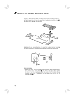
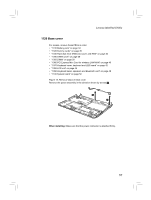
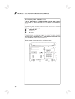
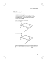
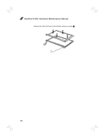
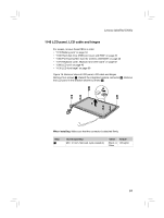
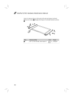
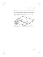
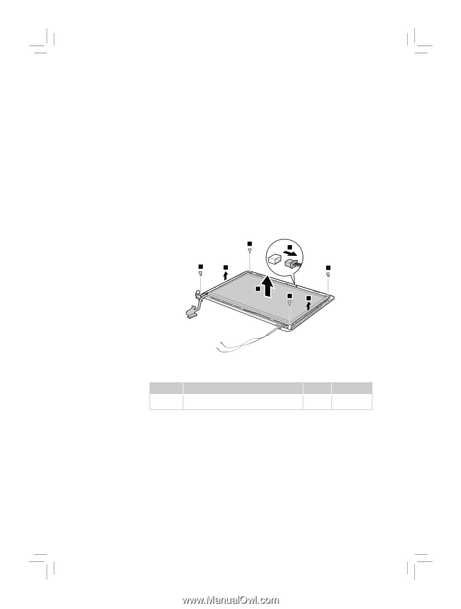
Lenovo IdeaPad S100c 1140 LCD panel, LCD cable and hinges For access, remove these FRUs in order: • "1010 Battery pack" on page 34 • "1030 Hard disk drive (HDD) slot cover and HDD" on page 36 • "1060 PCI Express Mini Card for wireless LAN/WAN" on page 40 • "1070 Keyboard cover, keyboard and LED board" on page 42 • "1080 LCD unit" on page 45 • "1130 LCD front bezel" on page 59 Figure 14. Removal steps of LCD panel, LCD cable and hinges Remove four screws a. Detach the integrated camera connector b. Remove the LCD panel in the direction shown by arrows c. 1 2 1 3 1 3 1 3 When installing: Make sure that the connector is attached firmly. Step a Screw (quantity) M2 × 3.5 mm, flat-head, nylok-coated (4) Color Torque Black or 1.85 kgfcm Silver 61
-
 1
1 -
2
-
3
-
4
-
5
-
6
-
7
-
8
-
9
-
10
-
11
-
12
-
13
-
14
-
15
-
16
-
17
-
18
-
19
-
20
-
21
-
22
-
23
-
24
-
25
-
26
-
27
-
28
-
29
-
30
-
31
-
32
-
33
-
34
-
35
-
36
-
37
-
38
-
39
-
40
-
41
-
42
-
43
-
44
-
45
-
46
-
47
-
48
-
49
-
50
-
51
-
52
-
53
-
54
-
55
-
56
-
57
-
58
-
59
-
 60
60 -
 61
61 -
 62
62 -
 63
63 -
 64
64 -
 65
65 -
 66
66 -
 67
67 -
 68
68 -
 69
69 -
 70
70 -
71
-
72
-
73
-
74
-
75
-
76
-
77
-
78
-
79
-
80
-
81
-
82
-
83
-
84
-
85
-
86
-
87
-
88
-
89
 |
 |
61
Lenovo IdeaPad S100c
1140 LCD panel, LCD cable and hinges
For access, remove these FRUs in order:
“1010 Battery pack” on page 34
•
“1030 Hard disk drive (HDD) slot cover and HDD” on page 36
•
“1060 PCI Express Mini Card for wireless LAN/WAN” on page 40
•
“1070 Keyboard cover, keyboard and LED board” on page 42
•
“1080 LCD unit” on page 45
•
“1130 LCD front bezel” on page 59
•
Figure 14. Removal steps of LCD panel, LCD cable and hinges
Remove four screws
a
. Detach the integrated camera connector
b
. Remove
the LCD panel in the direction shown by arrows
c
.
1
1
1
1
3
3
3
2
When installing:
Make sure that the connector is attached
fi
rmly.
Step
Screw (quantity)
Color
Torque
a
M2 × 3.5 mm,
fl
at-head, nylok-coated (4)
Black or
Silver
1.85 kgfcm