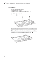
Lenovo IdeaPad S400u Hardware Maintanence Manual - Page 45
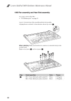
Removal steps of fan assembly and heat sink assembly continued
 |
View all Lenovo IdeaPad S400u manuals
Add to My Manuals
Save this manual to your list of manuals |
Page 45 highlights
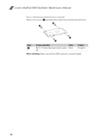
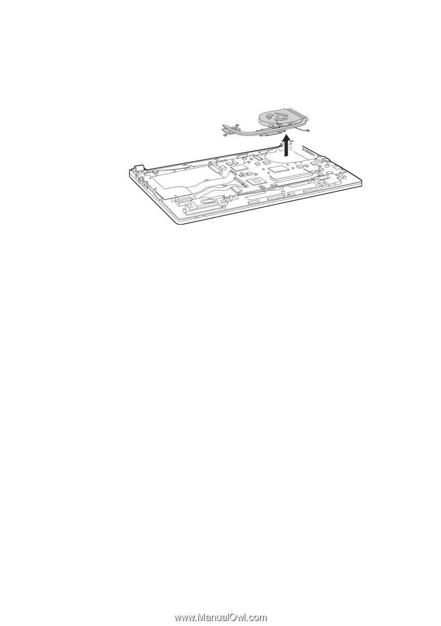
Lenovo IdeaPad S400 Figure 5. Removal steps of fan assembly and heat sink assembly (continued) Lift the fan assembly and heat sink assembly in the direction shown by arrow d. Be careful not to damage the connector. d 41
-
 1
1 -
2
-
3
-
4
-
5
-
6
-
7
-
8
-
9
-
10
-
11
-
12
-
13
-
14
-
15
-
16
-
17
-
18
-
19
-
20
-
21
-
22
-
23
-
24
-
25
-
26
-
27
-
28
-
29
-
30
-
31
-
32
-
33
-
34
-
35
-
36
-
37
-
38
-
39
-
 40
40 -
 41
41 -
 42
42 -
 43
43 -
 44
44 -
 45
45 -
 46
46 -
 47
47 -
 48
48 -
 49
49 -
 50
50 -
51
-
52
-
53
-
54
-
55
-
56
-
57
-
58
-
59
-
60
-
61
-
62
-
63
-
64
-
65
-
66
-
67
-
68
-
69
-
70
-
71
-
72
-
73
-
74
-
75
-
76
-
77
-
78
-
79
-
80
-
81
-
82
-
83
 |
 |
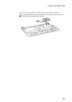
Lenovo IdeaPad S400
41
Figure 5. Removal steps of fan assembly and heat sink assembly (continued)
Lift the fan assembly and heat sink assembly in the direction shown by arrow
. Be careful not to damage the connector.
d
d