Lenovo IdeaPad U460S Lenovo IdeaPad U460 Hardware Maintenance Manual V2.0 - Page 60
Attention, When installing, too much or too less grease application can cause a thermal problem due
 |
View all Lenovo IdeaPad U460S manuals
Add to My Manuals
Save this manual to your list of manuals |
Page 60 highlights
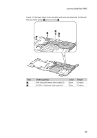
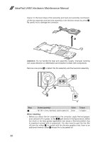
IdeaPad U460 Hardware Maintenance Manual Figure 12. Removal steps of fan assembly and heat sink assembly (continued) Lift the fan assembly and heat sink assembly in the direction shown by arrow 4. Be careful not to damage the connector. 4 Attention: Do not handle the heat sink assembly roughly. Improper handling can cause distortion or deformation and imperfect contact with components. Remove one screw 5 to detach the fan assembly and the heat sink assembly. d ab 5 c Step 5 Screw (quantity) Color M1.98 × 3 mm, flat-head, nylok-coated (1) Silver Torque 1.5 kgfcm When installing: •• Before you attach the fan assembly to the computer, apply thermal grease, at an amount of 0.2 grams, to the a b part shown in the figure above. Either too much or too less grease application can cause a thermal problem due to imperfect contact with a component. You also need to peel the thin film off from the rubber c . In models with the discrete graphics chip, there is an additional thermal rubber whose film to be peeled off. 56
-
 1
1 -
2
-
3
-
4
-
5
-
6
-
7
-
8
-
9
-
10
-
11
-
12
-
13
-
14
-
15
-
16
-
17
-
18
-
19
-
20
-
21
-
22
-
23
-
24
-
25
-
26
-
27
-
28
-
29
-
30
-
31
-
32
-
33
-
34
-
35
-
36
-
37
-
38
-
39
-
40
-
41
-
42
-
43
-
44
-
45
-
46
-
47
-
48
-
49
-
50
-
51
-
52
-
53
-
54
-
 55
55 -
 56
56 -
 57
57 -
 58
58 -
 59
59 -
 60
60 -
 61
61 -
 62
62 -
 63
63 -
 64
64 -
 65
65 -
66
-
67
-
68
-
69
-
70
-
71
-
72
-
73
-
74
-
75
-
76
-
77
-
78
-
79
-
80
-
81
-
82
-
83
-
84
-
85
-
86
-
87
-
88
 |
 |
