Lenovo J100 Hardware Maintenance Manual - Page 133
installing
 |
View all Lenovo J100 manuals
Add to My Manuals
Save this manual to your list of manuals |
Page 133 highlights
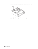
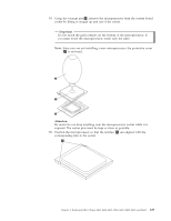
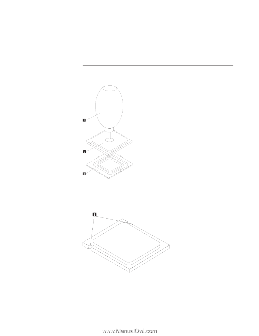
14. Using the vacuum pen 1 , remove the microprocessor from the system board socket by lifting it straight up and out of the socket. Important Do not touch the gold contacts on the bottom of the microprocessor. If you must touch the microprocessor, touch only the sides. Note: Since you are not installing a new microprocessor, the protective cover 3 is not used. Attention: Be careful to not drop anything onto the microprocessor socket while it is exposed. The socket pins must be kept as clean as possible. 15. Position the microprocessor so that the notches 1 are aligned with the corresponding tabs in the socket. Chapter 9. Replacing FRUs (Types 8453, 8454, 8455, 8456, 8457, 8458, 8459, and 8460) 127
-
 1
1 -
2
-
3
-
4
-
5
-
6
-
7
-
8
-
9
-
10
-
11
-
12
-
13
-
14
-
15
-
16
-
17
-
18
-
19
-
20
-
21
-
22
-
23
-
24
-
25
-
26
-
27
-
28
-
29
-
30
-
31
-
32
-
33
-
34
-
35
-
36
-
37
-
38
-
39
-
40
-
41
-
42
-
43
-
44
-
45
-
46
-
47
-
48
-
49
-
50
-
51
-
52
-
53
-
54
-
55
-
56
-
57
-
58
-
59
-
60
-
61
-
62
-
63
-
64
-
65
-
66
-
67
-
68
-
69
-
70
-
71
-
72
-
73
-
74
-
75
-
76
-
77
-
78
-
79
-
80
-
81
-
82
-
83
-
84
-
85
-
86
-
87
-
88
-
89
-
90
-
91
-
92
-
93
-
94
-
95
-
96
-
97
-
98
-
99
-
100
-
101
-
102
-
103
-
104
-
105
-
106
-
107
-
108
-
109
-
110
-
111
-
112
-
113
-
114
-
115
-
116
-
117
-
118
-
119
-
120
-
121
-
122
-
123
-
124
-
125
-
126
-
127
-
 128
128 -
 129
129 -
 130
130 -
 131
131 -
 132
132 -
 133
133 -
 134
134 -
 135
135 -
 136
136 -
 137
137 -
 138
138 -
139
-
140
-
141
-
142
-
143
-
144
-
145
-
146
-
147
-
148
-
149
-
150
-
151
-
152
-
153
-
154
-
155
-
156
-
157
-
158
-
159
-
160
-
161
-
162
-
163
-
164
-
165
-
166
-
167
-
168
-
169
-
170
-
171
-
172
-
173
-
174
-
175
-
176
-
177
-
178
-
179
-
180
-
181
-
182
-
183
-
184
-
185
-
186
-
187
-
188
-
189
-
190
-
191
-
192
-
193
-
194
-
195
-
196
-
197
-
198
-
199
-
200
-
201
-
202
-
203
-
204
-
205
-
206
-
207
-
208
-
209
-
210
-
211
-
212
-
213
-
214
-
215
-
216
-
217
-
218
 |
 |
14.
Using
the
vacuum
pen
±1²
,
remove
the
microprocessor
from
the
system
board
socket
by
lifting
it
straight
up
and
out
of
the
socket.
Important
Do
not
touch
the
gold
contacts
on
the
bottom
of
the
microprocessor.
If
you
must
touch
the
microprocessor,
touch
only
the
sides.
Note:
Since
you
are
not
installing
a
new
microprocessor,
the
protective
cover
±3²
is
not
used.
Attention:
Be
careful
to
not
drop
anything
onto
the
microprocessor
socket
while
it
is
exposed.
The
socket
pins
must
be
kept
as
clean
as
possible.
15.
Position
the
microprocessor
so
that
the
notches
±1²
are
aligned
with
the
corresponding
tabs
in
the
socket.
Chapter
9.
Replacing
FRUs
(Types
8453,
8454,
8455,
8456,
8457,
8458,
8459,
and
8460)
127