Lenovo J100 Hardware Maintenance Manual - Page 148
chassis.
 |
View all Lenovo J100 manuals
Add to My Manuals
Save this manual to your list of manuals |
Page 148 highlights
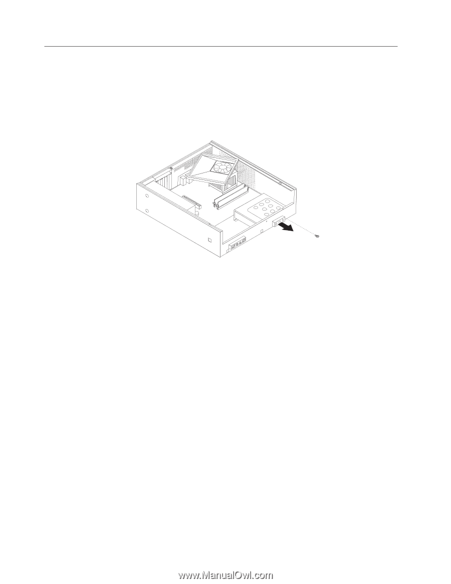
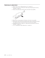
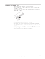
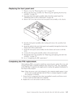
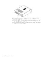
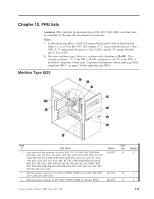
Replacing the power switch/ LED assembly 1. Remove cover. See "Removing the cover" on page 114. 2. Remove the drive bay assembly. See "Removing and replacing the drive bay assembly" on page 119. 3. Remove the hard disk drive. See "Replacing the hard disk drive" on page 139. 4. Disconnect the power switch/LED assembly cable from the system board. See "Identifying parts on the system board" on page 116. 5. Remove the screw that secures the power switch/LED assembly to the chassis. 6. Note the power switch/LED assembly cable routing and remove the assembly from the chassis. 7. Route the cable for the new power switch/LED assembly through the hole in the chassis and to the system board. 8. Install the power switch/LED assembly into the chassis and secure the assembly with the screw. 9. Connect the power switch/LED cable to the system board. 10. Reinstall the hard disk drive. See "Replacing the hard disk drive" on page 139. 11. Reinstall the drive bay assembly. See "Removing and replacing the drive bay assembly" on page 119. 12. Go to "Completing the FRU replacement." on page 143. 142 Lenovo 3000 J Series
-
 1
1 -
2
-
3
-
4
-
5
-
6
-
7
-
8
-
9
-
10
-
11
-
12
-
13
-
14
-
15
-
16
-
17
-
18
-
19
-
20
-
21
-
22
-
23
-
24
-
25
-
26
-
27
-
28
-
29
-
30
-
31
-
32
-
33
-
34
-
35
-
36
-
37
-
38
-
39
-
40
-
41
-
42
-
43
-
44
-
45
-
46
-
47
-
48
-
49
-
50
-
51
-
52
-
53
-
54
-
55
-
56
-
57
-
58
-
59
-
60
-
61
-
62
-
63
-
64
-
65
-
66
-
67
-
68
-
69
-
70
-
71
-
72
-
73
-
74
-
75
-
76
-
77
-
78
-
79
-
80
-
81
-
82
-
83
-
84
-
85
-
86
-
87
-
88
-
89
-
90
-
91
-
92
-
93
-
94
-
95
-
96
-
97
-
98
-
99
-
100
-
101
-
102
-
103
-
104
-
105
-
106
-
107
-
108
-
109
-
110
-
111
-
112
-
113
-
114
-
115
-
116
-
117
-
118
-
119
-
120
-
121
-
122
-
123
-
124
-
125
-
126
-
127
-
128
-
129
-
130
-
131
-
132
-
133
-
134
-
135
-
136
-
137
-
138
-
139
-
140
-
141
-
142
-
 143
143 -
 144
144 -
 145
145 -
 146
146 -
 147
147 -
 148
148 -
 149
149 -
 150
150 -
 151
151 -
 152
152 -
 153
153 -
154
-
155
-
156
-
157
-
158
-
159
-
160
-
161
-
162
-
163
-
164
-
165
-
166
-
167
-
168
-
169
-
170
-
171
-
172
-
173
-
174
-
175
-
176
-
177
-
178
-
179
-
180
-
181
-
182
-
183
-
184
-
185
-
186
-
187
-
188
-
189
-
190
-
191
-
192
-
193
-
194
-
195
-
196
-
197
-
198
-
199
-
200
-
201
-
202
-
203
-
204
-
205
-
206
-
207
-
208
-
209
-
210
-
211
-
212
-
213
-
214
-
215
-
216
-
217
-
218
 |
 |