Lenovo K450e Lenovo K4 Series Hardware Maintenance Manual - Page 30
Replacingamemorymodule
 |
View all Lenovo K450e manuals
Add to My Manuals
Save this manual to your list of manuals |
Page 30 highlights
Step 2. Remove the front bezel by releasing the three plastic tabs inside the chassis and pulling the bezel out as shown. Step 3. To reattach the bezel, align the plastic tabs on the bottom of the bezel with the corresponding holes in the chassis, and then snap it into position. Replacing a memory module Note: For this procedure, it helps to lay the computer flat. To replace a memory module: Step 1. Step 2. Step 3. Remove the computer cover. Refer to "Removing the computer cover". Locate the memory module connectors. Refer to "Locating components". Remove the memory module to be replaced by opening the retaining clips as shown. 26 Lenovo K4 SeriesHardware Maintenance Manual
-
 1
1 -
2
-
3
-
4
-
5
-
6
-
7
-
8
-
9
-
10
-
11
-
12
-
13
-
14
-
15
-
16
-
17
-
18
-
19
-
20
-
21
-
22
-
23
-
24
-
 25
25 -
 26
26 -
 27
27 -
 28
28 -
 29
29 -
 30
30 -
 31
31 -
 32
32 -
 33
33 -
 34
34 -
 35
35 -
36
-
37
-
38
-
39
-
40
-
41
-
42
-
43
-
44
-
45
-
46
-
47
-
48
-
49
 |
 |

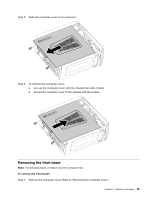
Step 2. Remove the front bezel by releasing the three plastic tabs inside the chassis and pulling the bezel
out as shown.
Step3.Toreattachthebezel,aligntheplastictabsonthebottomofthebezelwiththecorrespondingholes
in the chassis, and then snap it into position.
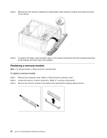
Replacingamemorymodule
Note:
For this procedure, it helps to lay the computer flat.
Toreplaceamemorymodule:
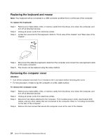
Step 1. Remove the computer cover. Refer to “Removing the computer cover”.
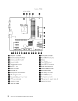
Step 2. Locate the memory module connectors. Refer to “Locating components”.
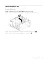
Step 3. Remove the memory module to be replaced by opening the retaining clips as shown.
26
Lenovo K4 SeriesHardware Maintenance Manual