Lenovo NetVista A40p Hardware Maintenance Manual for NetVista 6018, 6058, 6059 - Page 158
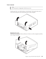
Power supply removal, The power supply is attached to the base of the chassis by a latch on
 |
View all Lenovo NetVista A40p manuals
Add to My Manuals
Save this manual to your list of manuals |
Page 158 highlights
2. Press the two side rail tabs and push the HD from the bottom. Pull the HD out. 3. When replacing the drive cage into its horizontal position, be sure place the cage latch back to its regular horizontal position. This is necessary so that the machine cover will fit properly. Power supply removal 1. Remove the four screws that hold the power supply to the back of the chassis. 2. The power supply is attached to the base of the chassis by a latch on the front. Slide the power supply forward to dislatch if from the chassis. 144 Hardware Maintenance Manual: IBM NetVista Computer Types 6058, 6059, 6269, 6568, 6569, 6578, 6579, 6648, 6649
-
 1
1 -
2
-
3
-
4
-
5
-
6
-
7
-
8
-
9
-
10
-
11
-
12
-
13
-
14
-
15
-
16
-
17
-
18
-
19
-
20
-
21
-
22
-
23
-
24
-
25
-
26
-
27
-
28
-
29
-
30
-
31
-
32
-
33
-
34
-
35
-
36
-
37
-
38
-
39
-
40
-
41
-
42
-
43
-
44
-
45
-
46
-
47
-
48
-
49
-
50
-
51
-
52
-
53
-
54
-
55
-
56
-
57
-
58
-
59
-
60
-
61
-
62
-
63
-
64
-
65
-
66
-
67
-
68
-
69
-
70
-
71
-
72
-
73
-
74
-
75
-
76
-
77
-
78
-
79
-
80
-
81
-
82
-
83
-
84
-
85
-
86
-
87
-
88
-
89
-
90
-
91
-
92
-
93
-
94
-
95
-
96
-
97
-
98
-
99
-
100
-
101
-
102
-
103
-
104
-
105
-
106
-
107
-
108
-
109
-
110
-
111
-
112
-
113
-
114
-
115
-
116
-
117
-
118
-
119
-
120
-
121
-
122
-
123
-
124
-
125
-
126
-
127
-
128
-
129
-
130
-
131
-
132
-
133
-
134
-
135
-
136
-
137
-
138
-
139
-
140
-
141
-
142
-
143
-
144
-
145
-
146
-
147
-
148
-
149
-
150
-
151
-
152
-
 153
153 -
 154
154 -
 155
155 -
 156
156 -
 157
157 -
 158
158 -
 159
159 -
 160
160 -
 161
161 -
 162
162 -
 163
163 -
164
-
165
-
166
-
167
-
168
-
169
-
170
-
171
-
172
-
173
-
174
-
175
-
176
-
177
-
178
-
179
-
180
-
181
-
182
-
183
-
184
-
185
-
186
-
187
-
188
-
189
-
190
-
191
-
192
-
193
-
194
-
195
-
196
-
197
-
198
-
199
-
200
-
201
-
202
-
203
-
204
-
205
-
206
-
207
-
208
-
209
-
210
-
211
-
212
-
213
-
214
-
215
-
216
-
217
-
218
-
219
-
220
-
221
-
222
-
223
-
224
-
225
-
226
-
227
-
228
-
229
-
230
-
231
-
232
-
233
-
234
-
235
-
236
-
237
-
238
-
239
-
240
-
241
-
242
-
243
-
244
-
245
-
246
-
247
-
248
 |
 |
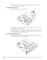
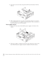
2.
Press the two side rail tabs and push the HD from the bottom. Pull the
HD out.
3.
When replacing the drive cage into its horizontal position, be sure place
the cage latch back to its regular horizontal position. This is necessary so
that the machine cover will fit properly.
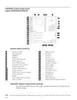
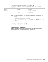
Power supply removal
1.
Remove the four screws that hold the power supply to the back of the
chassis.
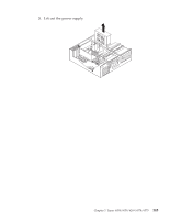
2.
The power supply is attached to the base of the chassis by a latch on the
front. Slide the power supply forward to dislatch if from the chassis.
144
Hardware Maintenance Manual: IBM NetVista Computer Types 6058, 6059, 6269, 6568, 6569, 6578, 6579, 6648,
6649