Lenovo NetVista A40p Hardware Maintenance Manual (HMM) for NetVista 2271, 6840 - Page 35
A40/A40P/A40i system board layout, System board locations, System board jumper settings
 |
View all Lenovo NetVista A40p manuals
Add to My Manuals
Save this manual to your list of manuals |
Page 35 highlights
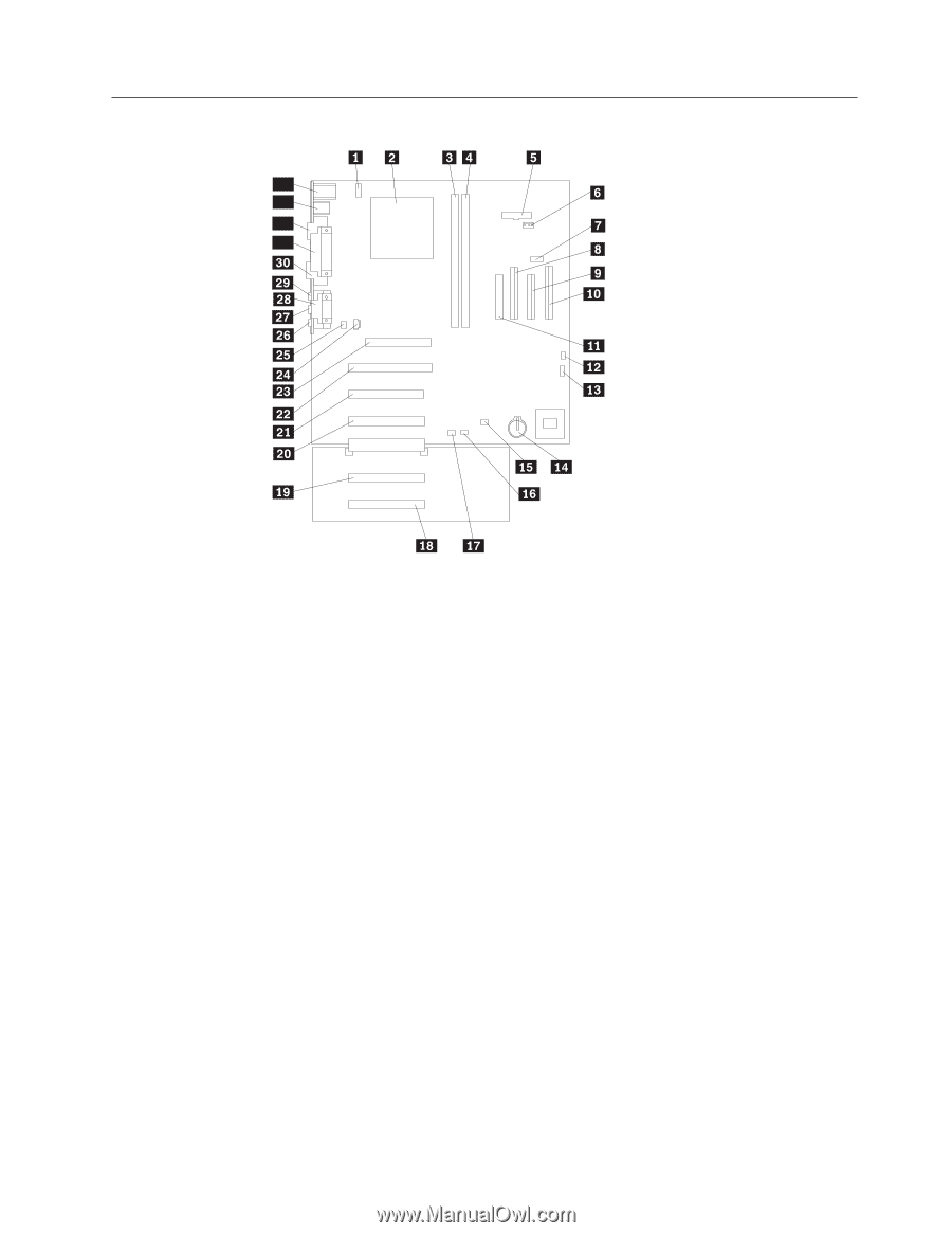
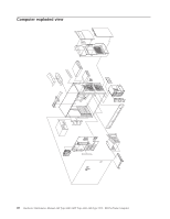
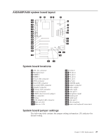
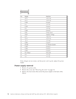
A40/A40P/A40i system board layout 34 33 32 31 System board locations 1 CPU fan connector 2 Microprocessor 3 DIMM 0 4 DIMM 1 5 Power LED connector 6 RFID connector 7 Front USB connector 8 Secondary IDE connector 9 Diskette connector 10 Primary IDE connector 11 Power connector 12 CMOS clear/recovery jumper 13 Fan connector 14 Battery 15 SCSI adapter LED connector 16 Alert on LAN 17 Wake on LAN 18 PCI slot 5 19 PCI slot 4 20 PCI slot 3 21 PCI slot 2 22 PCI slot 1 23 AGP slot 24 CD-ROM audio 25 Speaker connector 26 Audio output 27 Audio input 28 Serial port 2 29 Microphone input 30 Monitor port 31 Parallel port 32 Serial port 1 33 USB connectors 34 Mouse and keyboard connectors System board jumper settings The following table contains the jumper setting information. (D) indicates the default setting. Chapter 5. FRU Replacements 29
-
 1
1 -
2
-
3
-
4
-
5
-
6
-
7
-
8
-
9
-
10
-
11
-
12
-
13
-
14
-
15
-
16
-
17
-
18
-
19
-
20
-
21
-
22
-
23
-
24
-
25
-
26
-
27
-
28
-
29
-
 30
30 -
 31
31 -
 32
32 -
 33
33 -
 34
34 -
 35
35 -
 36
36 -
 37
37 -
 38
38 -
 39
39 -
 40
40 -
41
-
42
-
43
-
44
-
45
-
46
-
47
-
48
-
49
-
50
-
51
-
52
-
53
-
54
-
55
-
56
-
57
-
58
-
59
-
60
-
61
-
62
-
63
-
64
-
65
-
66
-
67
-
68
-
69
-
70
-
71
-
72
-
73
-
74
-
75
-
76
-
77
-
78
-
79
-
80
-
81
-
82
-
83
-
84
-
85
-
86
-
87
-
88
-
89
-
90
-
91
-
92
-
93
-
94
-
95
-
96
-
97
-
98
-
99
-
100
-
101
-
102
-
103
-
104
-
105
-
106
-
107
-
108
-
109
-
110
-
111
-
112
-
113
-
114
-
115
-
116
-
117
-
118
-
119
-
120
-
121
-
122
-
123
-
124
-
125
-
126
-
127
-
128
-
129
-
130
-
131
-
132
-
133
-
134
-
135
-
136
-
137
-
138
-
139
-
140
-
141
-
142
-
143
-
144
-
145
-
146
-
147
-
148
 |
 |