Lenovo Q150 Lenovo IdeaCentre Q150 Hardware Maintenance Manual V2.0
Lenovo Q150 Manual
 |
View all Lenovo Q150 manuals
Add to My Manuals
Save this manual to your list of manuals |
Lenovo Q150 manual content summary:
- Lenovo Q150 | Lenovo IdeaCentre Q150 Hardware Maintenance Manual V2.0 - Page 1
safety...4 Electrical safety...5 Safety inspection guide 7 Handling electrostatic discharge-sensitive devices 8 Grounding requirements 8 Safety notices...9 Chapter 3. General information 12 Specifications...12 Chapter 4. General Checkout 13 Problem determination tips 14 Chapter 5. Using - Lenovo Q150 | Lenovo IdeaCentre Q150 Hardware Maintenance Manual V2.0 - Page 2
Manual Chapter 6. Symptom-to-FRU Index 19 Hard disk drive boot error 19 Power Supply Problems 20 POST error codes...20 Undetermined problems 22 Chapter 7. Locations 23 Locating components and connectors 23 Chapter 8. Replacing hardware 25 Removing the computer cover 25 Replacing a memory - Lenovo Q150 | Lenovo IdeaCentre Q150 Hardware Maintenance Manual V2.0 - Page 3
service and reference information for Lenovo IdeaCentre Q computers listed on the cover. It is intended only for trained servicers who are familiar with Lenovo computer products. Before servicing a Lenovo product, be sure to read the Safety Information. This manual includes a complete FRU part - Lenovo Q150 | Lenovo IdeaCentre Q150 Hardware Maintenance Manual V2.0 - Page 4
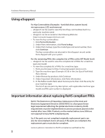
, LCD, and memory) •• eSupport can be used to view the list of key commodities built in a particular machine serial. •• eSupport can be accessed at the following Web site: http://consumersupport.lenovo.com •• To view the key commodities: 1. Click Parts information. 2. Under Parts information, click - Lenovo Q150 | Lenovo IdeaCentre Q150 Hardware Maintenance Manual V2.0 - Page 5
to support Lenovo's requirements and schedule. Products sold in 2005, will contain some RoHS compliant FRUs. The following statement pertains to these products and any product Lenovo produces containing RoHS compliant parts. RoHS compliant Lenovo IdeaCentre Q parts have unique FRU part numbers - Lenovo Q150 | Lenovo IdeaCentre Q150 Hardware Maintenance Manual V2.0 - Page 6
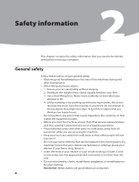
Maintenance Manual Safety information 2 This chapter contains the safety information that you need to be familiar with before servicing hazardous position. •• Place removed covers and other parts in a safe place, away from all personnel, while you are servicing the machine. •• Keep your tool case - Lenovo Q150 | Lenovo IdeaCentre Q150 Hardware Maintenance Manual V2.0 - Page 7
in any other conditions that might be hazardous to your eyes. •• After service, reinstall all safety shields, guards, labels, and ground wires. Replace any modems before you open the server/workstation covers, unless instructed otherwise in the installation and configuration procedures. Observe the - Lenovo Q150 | Lenovo IdeaCentre Q150 Hardware Maintenance Manual V2.0 - Page 8
Hardware Maintenance Manual •• If when you work with very high voltages; these instructions are in the safety sections of maintenance information. touching can cause personal injury and machine damage. •• Do not service the following parts with the power on when they are removed from their normal - Lenovo Q150 | Lenovo IdeaCentre Q150 Hardware Maintenance Manual V2.0 - Page 9
installed to protect users and service personnel from injury. This guide addresses only those items. continue without first correcting the problem. Consider these conditions and the cord should be the appropriate type as specified in the parts listings. c. Insulation must not be frayed or worn. - Lenovo Q150 | Lenovo IdeaCentre Q150 Hardware Maintenance Manual V2.0 - Page 10
Hardware Maintenance Manual Handling electrostatic discharge-sensitive devices Any computer part containing transistors or integrated circuits , such as those listed below, to provide protection that meets the specific service requirement. Note: The use of a grounding system is desirable but not - Lenovo Q150 | Lenovo IdeaCentre Q150 Hardware Maintenance Manual V2.0 - Page 11
damage. •• Disconnect the attached power cords, telecommunications systems, networks, and modems before you open the device covers, unless instructed otherwise in the installation and configuration procedures. •• Connect and disconnect cables as described in the following table when installing - Lenovo Q150 | Lenovo IdeaCentre Q150 Hardware Maintenance Manual V2.0 - Page 12
Hardware Maintenance Manual CAUTION: When replacing the lithium battery, use only Part Number 33F8354 or an equivalent type battery product could result in exposure to hazardous laser radiation. There are no serviceable parts inside the device. •• Use of controls or adjustments or performance of - Lenovo Q150 | Lenovo IdeaCentre Q150 Hardware Maintenance Manual V2.0 - Page 13
Chapter 2. Safety information CAUTION: Use safe practices when lifting. CAUTION: The power control button on the device and the power switch on the power supply do not turn off the electrical current supplied to the device. The device also might have more than one power cord. To remove all - Lenovo Q150 | Lenovo IdeaCentre Q150 Hardware Maintenance Manual V2.0 - Page 14
Manual General information 3 This chapter provides general information that applies to all machine types supported by this publication. Specifications This section lists the physical specifications for your computer. Type Lenovo IdeaCentre Q This section lists the physical specifications - Lenovo Q150 | Lenovo IdeaCentre Q150 Hardware Maintenance Manual V2.0 - Page 15
the computer you are servicing might have been rearranged beep, no memory count and checkpoint code display) when no errors are detected by POST. • To enable beep, memory count, and the following procedure to help determine the cause of the problem: 1. Power-off the computer and all external devices - Lenovo Q150 | Lenovo IdeaCentre Q150 Hardware Maintenance Manual V2.0 - Page 16
Hardware Maintenance Manual 5. Power-on the computer. • Look for displayed error codes • Listen for beep codes • Look for readable instructions or a main assist you in problem determination. If possible, have this information available when requesting assistance from Service Support and Engineering - Lenovo Q150 | Lenovo IdeaCentre Q150 Hardware Maintenance Manual V2.0 - Page 17
Chapter 4. General Checkout Comparing the configuration and software set-up between "working and non-working" systems will often lead to problem resolution. 15 - Lenovo Q150 | Lenovo IdeaCentre Q150 Hardware Maintenance Manual V2.0 - Page 18
Hardware Maintenance Manual Using the Setup Utility 5 The Setup Utility program is used to view and change the configuration settings of your computer, regardless of which operating system - Lenovo Q150 | Lenovo IdeaCentre Q150 Hardware Maintenance Manual V2.0 - Page 19
Chapter 5. Using the Setup Utility Selecting a startup device If your computer does not start up (boot) from a device such as the CD-ROM, diskette, or hard disk as expected, use one of the following procedures to select a startup device. Selecting a temporary startup device Use this procedure to - Lenovo Q150 | Lenovo IdeaCentre Q150 Hardware Maintenance Manual V2.0 - Page 20
Hardware Maintenance Manual Exiting from the Setup Utility program When you finish viewing or changing settings, press Esc to return to the Setup Utility program menu (you might - Lenovo Q150 | Lenovo IdeaCentre Q150 Hardware Maintenance Manual V2.0 - Page 21
FRUs to have available when servicing a computer. If you are unable to correct the problem using this index, go to "Undetermined problems" on page 27. Notes error message look for a description of your error symptoms in the first part of this index. Hard disk drive boot error A hard disk drive - Lenovo Q150 | Lenovo IdeaCentre Q150 Hardware Maintenance Manual V2.0 - Page 22
Hardware Maintenance Manual Error The boot sector on the start-up drive is corrupted. The • Checks the memory operation • Starts the video operation • Verifies that the boot drive is working If the POST detects a problem, an error message appears on the screen.A single problem can cause several - Lenovo Q150 | Lenovo IdeaCentre Q150 Hardware Maintenance Manual V2.0 - Page 23
Chapter 6. Symptom-to-FRU Index POST Error Message CMOS Date/Time Not Set CMOS Battery Low CMOS Checksum Bad Primary Master Hard Disk Error Primary Slave Hard Disk Error Secondary Master Hard Disk Error Secondary Slave Hard Disk Error Description/Action The CMOS Date and/or Time are invalid. This - Lenovo Q150 | Lenovo IdeaCentre Q150 Hardware Maintenance Manual V2.0 - Page 24
Hardware Maintenance Manual Undetermined problems If this computer has a parallel ATA hard disk drive a time. a. External devices (modem, printer, or mouse) b. Any adapters c. Memory modules d. Extended video memory e. External Cache f. External Cache RAM g. Hard disk drive h. Diskette drive 3. Power - Lenovo Q150 | Lenovo IdeaCentre Q150 Hardware Maintenance Manual V2.0 - Page 25
Internal components The following illustration shows the components inside your computer. 8 7 3 2 6 5 4 1 9 10 11 12 13 1 Front cover 5 System fan 2 Metal bracket 6 Memory 3 Hard disk drive 7 Motherboard 4 Hard disk drive bay 8 Rear cover 11 Wi-Fi shield 9 Wi-Fi module 12 Antenna 10 Wi - Lenovo Q150 | Lenovo IdeaCentre Q150 Hardware Maintenance Manual V2.0 - Page 26
basic computer functions and supports a variety of devices that are factory-installed or that you can install later. The following illustration shows the locations of parts on the system board. 1 2 3 4 15 5 14 13 6 12 11 7 10 9 8 1 GPU socket 2 CPU socket 3 Memory connector 4 Power switch - Lenovo Q150 | Lenovo IdeaCentre Q150 Hardware Maintenance Manual V2.0 - Page 27
5 minutes to let the computer cool down before removing the computer cover. To remove the computer cover: 1. Remove any media (diskettes, CDs, or memory cards) from the drives, shut down your operating system, turn off all attached devices, and the computer. 2. Unplug all power cords from electrical - Lenovo Q150 | Lenovo IdeaCentre Q150 Hardware Maintenance Manual V2.0 - Page 28
Hardware Maintenance Manual 4. Remove the screw that secures the base stand to the computer. 5. Place the computer on a flat surface. 26 - Lenovo Q150 | Lenovo IdeaCentre Q150 Hardware Maintenance Manual V2.0 - Page 29
Chapter 8. Replacing hardware 6. Remove the six screws that secure the computer cover to the chassis. 7. Slide the computer cover out to remove it. Replacing a memory module To remove the memory module: 1. Remove the computer cover. Refer to "Removing the computer cover". 27 - Lenovo Q150 | Lenovo IdeaCentre Q150 Hardware Maintenance Manual V2.0 - Page 30
Hardware Maintenance Manual 2. Push out the latches on both sides of the memory socket to release the memory module. 3. Gently pull the memory module upward to remove it from its socket. 4. Align and then insert the new memory module into socket and push down on the top edge of the memory module. - Lenovo Q150 | Lenovo IdeaCentre Q150 Hardware Maintenance Manual V2.0 - Page 31
Chapter 8. Replacing hardware Replacing the CPU heatsink and system fan Attention: The heatsink becomes very hot when the system is on. Never touch the heatsink with any metal or with your hands. To replace the CPU heatsink and system fan: 1. Remove the computer cover. Refer to "Removing the - Lenovo Q150 | Lenovo IdeaCentre Q150 Hardware Maintenance Manual V2.0 - Page 32
Hardware Maintenance Manual 4. Lift up the CPU heatsink and system fan to remove them from the motherboard. 5. Place the CPU heatsink upside down on a flat surface to prevent - Lenovo Q150 | Lenovo IdeaCentre Q150 Hardware Maintenance Manual V2.0 - Page 33
Chapter 8. Replacing hardware Replacing the hard disk drive To replace the hard disk drive: 1. Remove the computer cover. Refer to "Removing the computer cover". 2. Remove the four screws that secure the hard disk drive and bay to the motherboard. 3. Pull the hard disk drive and bay upward and pull - Lenovo Q150 | Lenovo IdeaCentre Q150 Hardware Maintenance Manual V2.0 - Page 34
Hardware Maintenance Manual 4. Remove the 4 screws that secure the hard disk drive to the drive Remove the computer cover. Refer to "Removing the computer cover". 2. Remove the memory module. Refer to "Replacing the memory module". 3. Remove the CPU heatsink and system fan. Refer to "Replacing the - Lenovo Q150 | Lenovo IdeaCentre Q150 Hardware Maintenance Manual V2.0 - Page 35
7. Lift up the metal bracket. Chapter 8. Replacing hardware 8. Remove the 2 screws that secure the motherboard to the chassis. 33 - Lenovo Q150 | Lenovo IdeaCentre Q150 Hardware Maintenance Manual V2.0 - Page 36
Hardware Maintenance Manual 9. Pull the motherboard out of the chassis. 10. Place the new motherboard into the chassis, align the screw holes in the motherboard with the mounting - Lenovo Q150 | Lenovo IdeaCentre Q150 Hardware Maintenance Manual V2.0 - Page 37
Chapter 8. Replacing hardware 4. Remove the antenna from the Wi-Fi module. 5. Remove the 2 screws that secure the Wi-Fi module to the motherboard. 6. Disconnect the Wi-Fi cable from the motherboard. 35 - Lenovo Q150 | Lenovo IdeaCentre Q150 Hardware Maintenance Manual V2.0 - Page 38
the computer, or in the Hardware Maintenance Manual (HMM) for the computer. To obtain copies of the Safety and Warranty Guide or HMM, go to the Support Web site at: http://consumersupport.lenovo.com. To replace the keyboard: 1. Remove any media (diskettes, CDs, or memory cards) from the drives, shut - Lenovo Q150 | Lenovo IdeaCentre Q150 Hardware Maintenance Manual V2.0 - Page 39
computer, or in the Hardware Maintenance Manual (HMM) for the computer. To obtain copies of the Safety and Warranty Guide or HMM, go to the Support Web site at: http://consumersupport.lenovo.com. To replace the mouse: 1. Remove any media (diskettes, CDs, or memory cards) from the drives, shut down - Lenovo Q150 | Lenovo IdeaCentre Q150 Hardware Maintenance Manual V2.0 - Page 40
cover and reconnect the cables, including telephone lines and power cables. Also, depending on the part that was replaced, you might need to confirm the updated information in the Setup Utility program. Refer to "Starting the Setup Utility" in the User Guide or in the Hardware Maintenance Manual. 38 - Lenovo Q150 | Lenovo IdeaCentre Q150 Hardware Maintenance Manual V2.0 - Page 41
Chapter 8. Replacing hardware To complete the installation (final step): 1. Ensure that all components have been reassembled correctly and that no tools or loose screws are left inside your computer. Refer to "Locating components and ports/sockets" for the location of the various components. 2. Make - Lenovo Q150 | Lenovo IdeaCentre Q150 Hardware Maintenance Manual V2.0 - Page 42
Hardware Maintenance Manual Additional Service Information 9 This chapter provides additional information that the service representative might Power Management (APM) BIOS mode is ignored. Not all operating systems support ACPI BIOS mode. Automatic Power-On features The Automatic Power-On features - Lenovo Q150 | Lenovo IdeaCentre Q150 Hardware Maintenance Manual V2.0 - Page 43
according to the instructions and requirements described in the manuals included with your computer. Lenovo will not assume responsibility for any loss incurred except those resulting from installation or operations carried out by Lenovo professional service staff. Lenovo has made every attempt - Lenovo Q150 | Lenovo IdeaCentre Q150 Hardware Maintenance Manual V2.0 - Page 44
table above includes the logo and registered trademarks of Lenovo and its partners. Other registered trademarks mentioned in any or all of the manuals included with your computer belong to the specific company respectively. The manual included with your computer is protected by copyright laws and
-
 1
1 -
 2
2 -
 3
3 -
 4
4 -
 5
5 -
 6
6 -
 7
7 -
8
-
9
-
10
-
11
-
12
-
13
-
14
-
15
-
16
-
17
-
18
-
19
-
20
-
21
-
22
-
23
-
24
-
25
-
26
-
27
-
28
-
29
-
30
-
31
-
32
-
33
-
34
-
35
-
36
-
37
-
38
-
39
-
40
-
41
-
42
-
43
-
44
 |
 |

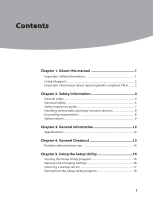
Contents
i
Contents
Chapter 1. About this manual
..............................................
1
Important
Safety Information
..............................................................................
1
Using eSupport
...........................................................................................................
2
Important information about replacing RoHS compliant FRUs
..........
2
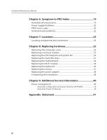
Chapter 2. Safety information
..............................................
4
General safety
..............................................................................................................
4
Electrical safety
............................................................................................................
5
Safety inspection guide
..........................................................................................
7
Handling electrostatic discharge-sensitive devices
.................................
8
Grounding requirements
......................................................................................
8
Safety notices
...............................................................................................................
9
Chapter 3. General information
.........................................
12
Specifications
............................................................................................................
12
Chapter 4. General Checkout
.............................................
13
Problem determination tips
.............................................................................
14
Chapter 5. Using the Setup Utility
.....................................
16
Starting the Setup Utility program
.................................................................
16
Viewing and changing settings
.......................................................................
16
Selecting a startup device
..................................................................................
17
Exiting from the Setup Utility program
........................................................
18