Lenovo SL410 User Manual - Page 127
For ThinkPad SL410 and L410 integrated models, ICH I/O Controller Hub
 |
UPC - 074450008602
View all Lenovo SL410 manuals
Add to My Manuals
Save this manual to your list of manuals |
Page 127 highlights
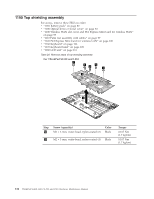
For access, remove these FRUs, in order: v "1010 Battery pack" on page 80 v "1020 ExpressCard blank bezel and Media Card blank bezel" on page 81 v "1030 Optical drive or travel cover" on page 83 v "1040 Thermal cover" on page 84 v "1050 Hard disk drive (HDD) assembly" on page 85 v "1060 DIMM" on page 87 v "1070 Fan assembly" on page 88 v "1080 CPU" on page 92 v "1090 SIM slot cover" on page 93 v "1100 Wireless WAN slot cover and PCI Express Mini Card for wireless WAN" on page 95 v "1110 Palm rest assembly with cables" on page 97 v "1120 PCI Express Mini Card for wireless LAN" on page 100 v "1130 Backup battery" on page 102 v "1140 Bluetooth daughter card (BDC-2)" on page 103 v "1150 Media Card Reader slot board and Media Card Reader cable assembly" on page 104 v "1160 Keyboard" on page 106 v "1170 Keyboard bezel" on page 109 v "1180 LCD unit" on page 111 v "1190 Top shielding assembly" on page 116 Table 30. Location of major sensitive components on the system board Following components soldered on the top side of the system board are extremely sensitive. When you service the system board, avoid any kind of rough handling. a GMCH (Integrated video chip) b CPU c ICH (I/O Controller Hub) d Video chip (only for discrete models) For ThinkPad SL410 and L410 integrated models: a b c Removing and replacing a FRU 119
-
 1
1 -
2
-
3
-
4
-
5
-
6
-
7
-
8
-
9
-
10
-
11
-
12
-
13
-
14
-
15
-
16
-
17
-
18
-
19
-
20
-
21
-
22
-
23
-
24
-
25
-
26
-
27
-
28
-
29
-
30
-
31
-
32
-
33
-
34
-
35
-
36
-
37
-
38
-
39
-
40
-
41
-
42
-
43
-
44
-
45
-
46
-
47
-
48
-
49
-
50
-
51
-
52
-
53
-
54
-
55
-
56
-
57
-
58
-
59
-
60
-
61
-
62
-
63
-
64
-
65
-
66
-
67
-
68
-
69
-
70
-
71
-
72
-
73
-
74
-
75
-
76
-
77
-
78
-
79
-
80
-
81
-
82
-
83
-
84
-
85
-
86
-
87
-
88
-
89
-
90
-
91
-
92
-
93
-
94
-
95
-
96
-
97
-
98
-
99
-
100
-
101
-
102
-
103
-
104
-
105
-
106
-
107
-
108
-
109
-
110
-
111
-
112
-
113
-
114
-
115
-
116
-
117
-
118
-
119
-
120
-
121
-
 122
122 -
 123
123 -
 124
124 -
 125
125 -
 126
126 -
 127
127 -
 128
128 -
 129
129 -
 130
130 -
 131
131 -
 132
132 -
133
-
134
-
135
-
136
-
137
-
138
-
139
-
140
-
141
-
142
-
143
-
144
-
145
-
146
-
147
-
148
-
149
-
150
-
151
-
152
-
153
-
154
-
155
-
156
-
157
-
158
-
159
-
160
-
161
-
162
-
163
-
164
-
165
-
166
-
167
-
168
-
169
-
170
-
171
-
172
-
173
-
174
-
175
-
176
-
177
-
178
-
179
-
180
-
181
-
182
-
183
-
184
-
185
-
186
-
187
-
188
 |
 |
