Lenovo ThinkPad Edge 15 Hardware Maintenance Manual - Page 91
System board assembly, Important notices for handling the system board, Diagnostics - bluetooth
 |
View all Lenovo ThinkPad Edge 15 manuals
Add to My Manuals
Save this manual to your list of manuals |
Page 91 highlights
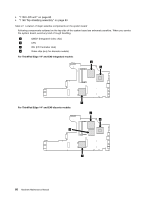
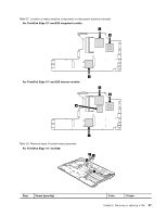
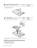
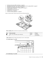
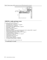
Table 26. Removal steps of top shielding assembly (continued) 1 M2 × 2 mm, wafer-head, nylon-coated (1) 2 M2 × 3 mm, wafer-head, nylon-coated (2) 3 M2 × 5 mm, wafer-head, nylon-coated (4) Silver Black Black 0.181 Nm (1.85 kgfcm) 0.181 Nm (1.85 kgfcm) 0.181 Nm (1.85 kgfcm) 1170 System board assembly Important notices for handling the system board: When handling the system board, bear the following in mind. • The system board has an accelerometer, which can be broken by applying several thousands of G-forces. Note: Dropping a system board from a height of as little as 6 inches so that it falls flat on a hard bench can subject the accelerometer to as much as 6,000 G's of shock. • Be careful not to drop the system board on a bench top that has a hard surface, such as metal, wood, or composite. • If a system board is dropped, you must test it, using PC-Doctor for DOS, to make sure that the HDD Active Protection SystemTM still functions (see below). Note: If the test shows that HDD Active Protection System is not functioning, be sure to document the drop in any reject report, and replace the system board. • Avoid rough handling of any kind. • At every point in the process, be sure not to drop or stack the system board. • If you put a system board down, be sure to put it only on a padded surface such as an ESD mat or conductive corrugated material. After replacing the system board, run PC-Doctor for DOS to make sure that HDD Active Protection System still functions. The procedure is as follows: 1. Place the computer on a horizontal surface. 2. Run Diagnostics ➙ ThinkPad Devices ➙ HDD Active Protection Test. Attention: Do not apply physical shock to the computer while the test is running. For access, remove these FRUs, in order: • "1010 Battery pack" on page 58 • "1020 Optical drive or travel cover" on page 58 • "1030 Thermal cover" on page 59 • "1040 Hard disk drive (HDD) assembly" on page 60 • "1050 DIMM" on page 61 • "1060 Fan assembly" on page 63 • "1070 CPU" on page 66 • "1080 Wireless WAN slot cover and PCI Express Mini Card for wireless WAN" on page 67 • "1090 Palm rest assembly with cables" on page 69 • "1100 PCI Express Mini Card for wireless LAN" on page 72 • "1110 Backup battery" on page 74 • "1120 Bluetooth daughter card (BDC-2)" on page 75 • "1130 Keyboard" on page 75 • "1140 Keyboard bezel" on page 78 Chapter 8. Removing or replacing a FRU 85
-
 1
1 -
2
-
3
-
4
-
5
-
6
-
7
-
8
-
9
-
10
-
11
-
12
-
13
-
14
-
15
-
16
-
17
-
18
-
19
-
20
-
21
-
22
-
23
-
24
-
25
-
26
-
27
-
28
-
29
-
30
-
31
-
32
-
33
-
34
-
35
-
36
-
37
-
38
-
39
-
40
-
41
-
42
-
43
-
44
-
45
-
46
-
47
-
48
-
49
-
50
-
51
-
52
-
53
-
54
-
55
-
56
-
57
-
58
-
59
-
60
-
61
-
62
-
63
-
64
-
65
-
66
-
67
-
68
-
69
-
70
-
71
-
72
-
73
-
74
-
75
-
76
-
77
-
78
-
79
-
80
-
81
-
82
-
83
-
84
-
85
-
 86
86 -
 87
87 -
 88
88 -
 89
89 -
 90
90 -
 91
91 -
 92
92 -
 93
93 -
 94
94 -
 95
95 -
 96
96 -
97
-
98
-
99
-
100
-
101
-
102
-
103
-
104
-
105
-
106
-
107
-
108
-
109
-
110
-
111
-
112
-
113
-
114
-
115
-
116
-
117
-
118
-
119
-
120
-
121
-
122
-
123
-
124
-
125
-
126
-
127
-
128
-
129
-
130
-
131
-
132
-
133
-
134
-
135
-
136
-
137
-
138
-
139
-
140
-
141
-
142
-
143
-
144
-
145
-
146
-
147
-
148
-
149
-
150
-
151
-
152
-
153
-
154
-
155
-
156
-
157
-
158
 |
 |
