Lenovo ThinkPad Edge E50 Hardware Maintenance Manual - Page 72
CPU
 |
View all Lenovo ThinkPad Edge E50 manuals
Add to My Manuals
Save this manual to your list of manuals |
Page 72 highlights
Table 13. Removal steps of fan assembly (continued) b a a 1070 CPU For access, remove these FRUs in order: • "1010 Battery pack" on page 58 • "1030 Thermal cover" on page 59 • "1060 Fan assembly" on page 63 Attention: CPU is extremely sensitive. When you service the CPU, avoid any kind of rough handling. Table 14. Removal steps of CPU Rotate the head of the screw in the direction shown by arrow 1 to release the lock; then remove the CPU 2 . 1 a 2 When installing: Place the CPU on the CPU socket, and then rotate the head of the screw in the direction shown by arrow a to secure the CPU. 66 Hardware Maintenance Manual
-
 1
1 -
2
-
3
-
4
-
5
-
6
-
7
-
8
-
9
-
10
-
11
-
12
-
13
-
14
-
15
-
16
-
17
-
18
-
19
-
20
-
21
-
22
-
23
-
24
-
25
-
26
-
27
-
28
-
29
-
30
-
31
-
32
-
33
-
34
-
35
-
36
-
37
-
38
-
39
-
40
-
41
-
42
-
43
-
44
-
45
-
46
-
47
-
48
-
49
-
50
-
51
-
52
-
53
-
54
-
55
-
56
-
57
-
58
-
59
-
60
-
61
-
62
-
63
-
64
-
65
-
66
-
 67
67 -
 68
68 -
 69
69 -
 70
70 -
 71
71 -
 72
72 -
 73
73 -
 74
74 -
 75
75 -
 76
76 -
 77
77 -
78
-
79
-
80
-
81
-
82
-
83
-
84
-
85
-
86
-
87
-
88
-
89
-
90
-
91
-
92
-
93
-
94
-
95
-
96
-
97
-
98
-
99
-
100
-
101
-
102
-
103
-
104
-
105
-
106
-
107
-
108
-
109
-
110
-
111
-
112
-
113
-
114
-
115
-
116
-
117
-
118
-
119
-
120
-
121
-
122
-
123
-
124
-
125
-
126
-
127
-
128
-
129
-
130
-
131
-
132
-
133
-
134
-
135
-
136
-
137
-
138
-
139
-
140
-
141
-
142
-
143
-
144
-
145
-
146
-
147
-
148
-
149
-
150
-
151
-
152
-
153
-
154
-
155
-
156
-
157
-
158
 |
 |

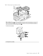
Table 13. Removal steps of fan assembly (continued)
b
a
a
1070 CPU
For access, remove these FRUs in order:
•
“1010 Battery pack” on page 58
•
“1030 Thermal cover” on page 59
•
“1060 Fan assembly” on page 63
Attention:
CPU is extremely sensitive. When you service the CPU, avoid any kind of rough handling.
Table 14. Removal steps of CPU
Rotate the head of the screw in the direction shown by arrow
1
to release the lock; then remove the CPU
2
.
1
2
a
When installing:
Place the CPU on the CPU socket, and then rotate the head of the screw in the direction shown
by arrow
a
to secure the CPU.
66
Hardware Maintenance Manual