Lenovo ThinkPad Edge E50 Hardware Maintenance Manual - Page 77
Table 17. Removal steps of palm rest assembly with cables continued, Table 18. Installation of palm
 |
View all Lenovo ThinkPad Edge E50 manuals
Add to My Manuals
Save this manual to your list of manuals |
Page 77 highlights
Table 17. Removal steps of palm rest assembly with cables (continued) 7 6 5 7 6 Table 18. Installation of palm rest assembly with cables When installing: 1. Attach the cables to the system board firmly. 2. Attach the palm rest so that the two small projections of the palm rest firmly fit into the guide holes of the keyboard bezel as shown in this figure. Chapter 8. Removing or replacing a FRU 71
-
 1
1 -
2
-
3
-
4
-
5
-
6
-
7
-
8
-
9
-
10
-
11
-
12
-
13
-
14
-
15
-
16
-
17
-
18
-
19
-
20
-
21
-
22
-
23
-
24
-
25
-
26
-
27
-
28
-
29
-
30
-
31
-
32
-
33
-
34
-
35
-
36
-
37
-
38
-
39
-
40
-
41
-
42
-
43
-
44
-
45
-
46
-
47
-
48
-
49
-
50
-
51
-
52
-
53
-
54
-
55
-
56
-
57
-
58
-
59
-
60
-
61
-
62
-
63
-
64
-
65
-
66
-
67
-
68
-
69
-
70
-
71
-
 72
72 -
 73
73 -
 74
74 -
 75
75 -
 76
76 -
 77
77 -
 78
78 -
 79
79 -
 80
80 -
 81
81 -
 82
82 -
83
-
84
-
85
-
86
-
87
-
88
-
89
-
90
-
91
-
92
-
93
-
94
-
95
-
96
-
97
-
98
-
99
-
100
-
101
-
102
-
103
-
104
-
105
-
106
-
107
-
108
-
109
-
110
-
111
-
112
-
113
-
114
-
115
-
116
-
117
-
118
-
119
-
120
-
121
-
122
-
123
-
124
-
125
-
126
-
127
-
128
-
129
-
130
-
131
-
132
-
133
-
134
-
135
-
136
-
137
-
138
-
139
-
140
-
141
-
142
-
143
-
144
-
145
-
146
-
147
-
148
-
149
-
150
-
151
-
152
-
153
-
154
-
155
-
156
-
157
-
158
 |
 |

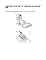
Table 17. Removal steps of palm rest assembly with cables (continued)
6
7
6
7
5
Table 18. Installation of palm rest assembly with cables
When installing:
1. Attach the cables to the system board firmly.
2. Attach the palm rest so that the two small projections of the palm rest firmly fit into the guide holes of the
keyboard bezel as shown in this figure.
Chapter 8
.
Removing or replacing a FRU
71