Lenovo ThinkPad R40 Hardware Maintenance Manual - Page 122
system, board, disconnect, Card/ExpressCard, slots, assembly, interposer, board., models, 0-in.,
 |
View all Lenovo ThinkPad R40 manuals
Add to My Manuals
Save this manual to your list of manuals |
Page 122 highlights
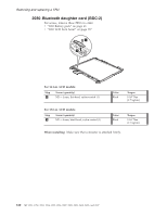
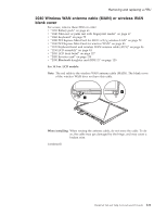
Removing and replacing a FRU 1 1 Step 1 Screw (quantity) M2 × 3 mm, flat-head, nylon-coated (2) Color Silver Torque 0.167 Nm (1.7 kgfcm) Turn the system board over, and then disconnect the PC Card/ExpressCard slots assembly a and the interposer card b from the system board. Note: Step 3 is only for models with a 15.0-in. LCD. Other models do not have the interposer card b . a 2 3 b When installing: Make sure that the connectors of the PC Card/Express Card slot assembly and of the interposer card are attached to the system board firmly. 116 MT 1951, 1952, 1953, 1954, 1955, 1956, 2007, 2008, 2009, 2613, 2623, and 2637
-
 1
1 -
2
-
3
-
4
-
5
-
6
-
7
-
8
-
9
-
10
-
11
-
12
-
13
-
14
-
15
-
16
-
17
-
18
-
19
-
20
-
21
-
22
-
23
-
24
-
25
-
26
-
27
-
28
-
29
-
30
-
31
-
32
-
33
-
34
-
35
-
36
-
37
-
38
-
39
-
40
-
41
-
42
-
43
-
44
-
45
-
46
-
47
-
48
-
49
-
50
-
51
-
52
-
53
-
54
-
55
-
56
-
57
-
58
-
59
-
60
-
61
-
62
-
63
-
64
-
65
-
66
-
67
-
68
-
69
-
70
-
71
-
72
-
73
-
74
-
75
-
76
-
77
-
78
-
79
-
80
-
81
-
82
-
83
-
84
-
85
-
86
-
87
-
88
-
89
-
90
-
91
-
92
-
93
-
94
-
95
-
96
-
97
-
98
-
99
-
100
-
101
-
102
-
103
-
104
-
105
-
106
-
107
-
108
-
109
-
110
-
111
-
112
-
113
-
114
-
115
-
116
-
 117
117 -
 118
118 -
 119
119 -
 120
120 -
 121
121 -
 122
122 -
 123
123 -
 124
124 -
 125
125 -
 126
126 -
 127
127 -
128
-
129
-
130
-
131
-
132
-
133
-
134
-
135
-
136
-
137
-
138
-
139
-
140
-
141
-
142
-
143
-
144
-
145
-
146
-
147
-
148
-
149
-
150
-
151
-
152
-
153
-
154
-
155
-
156
-
157
-
158
-
159
-
160
-
161
-
162
-
163
-
164
-
165
-
166
-
167
-
168
-
169
-
170
-
171
-
172
-
173
-
174
-
175
-
176
-
177
-
178
-
179
-
180
-
181
-
182
-
183
-
184
-
185
-
186
-
187
-
188
-
189
-
190
-
191
-
192
-
193
-
194
-
195
-
196
-
197
-
198
-
199
-
200
-
201
-
202
-
203
-
204
-
205
-
206
-
207
-
208
-
209
-
210
-
211
-
212
-
213
-
214
-
215
-
216
-
217
-
218
-
219
-
220
-
221
-
222
-
223
-
224
-
225
-
226
 |
 |
1
1
Step
Screw
(quantity)
Color
Torque
±1²
M2
×
3
mm,
flat-head,
nylon-coated
(2)
Silver
0.167
Nm
(1.7
kgfcm)
Turn
the
system
board
over,
and
then
disconnect
the
PC
Card/ExpressCard
slots
assembly
±a²
and
the
interposer
card
±b²
from
the
system
board.
Note:
Step
±3²
is
only
for
models
with
a
15.0-in.
LCD.
Other
models
do
not
have
the
interposer
card
±b²
.
2
a
b
3
When
installing:
Make
sure
that
the
connectors
of
the
PC
Card/Express
Card
slot
assembly
and
of
the
interposer
card
are
attached
to
the
system
board
firmly.
Removing
and
replacing
a
FRU
116
MT
1951,
1952,
1953,
1954,
1955,
1956,
2007,
2008,
2009,
2613,
2623,
and
2637