Lenovo ThinkPad T420 Hardware Maintenance Manual - Page 111
CPU
 |
View all Lenovo ThinkPad T420 manuals
Add to My Manuals
Save this manual to your list of manuals |
Page 111 highlights
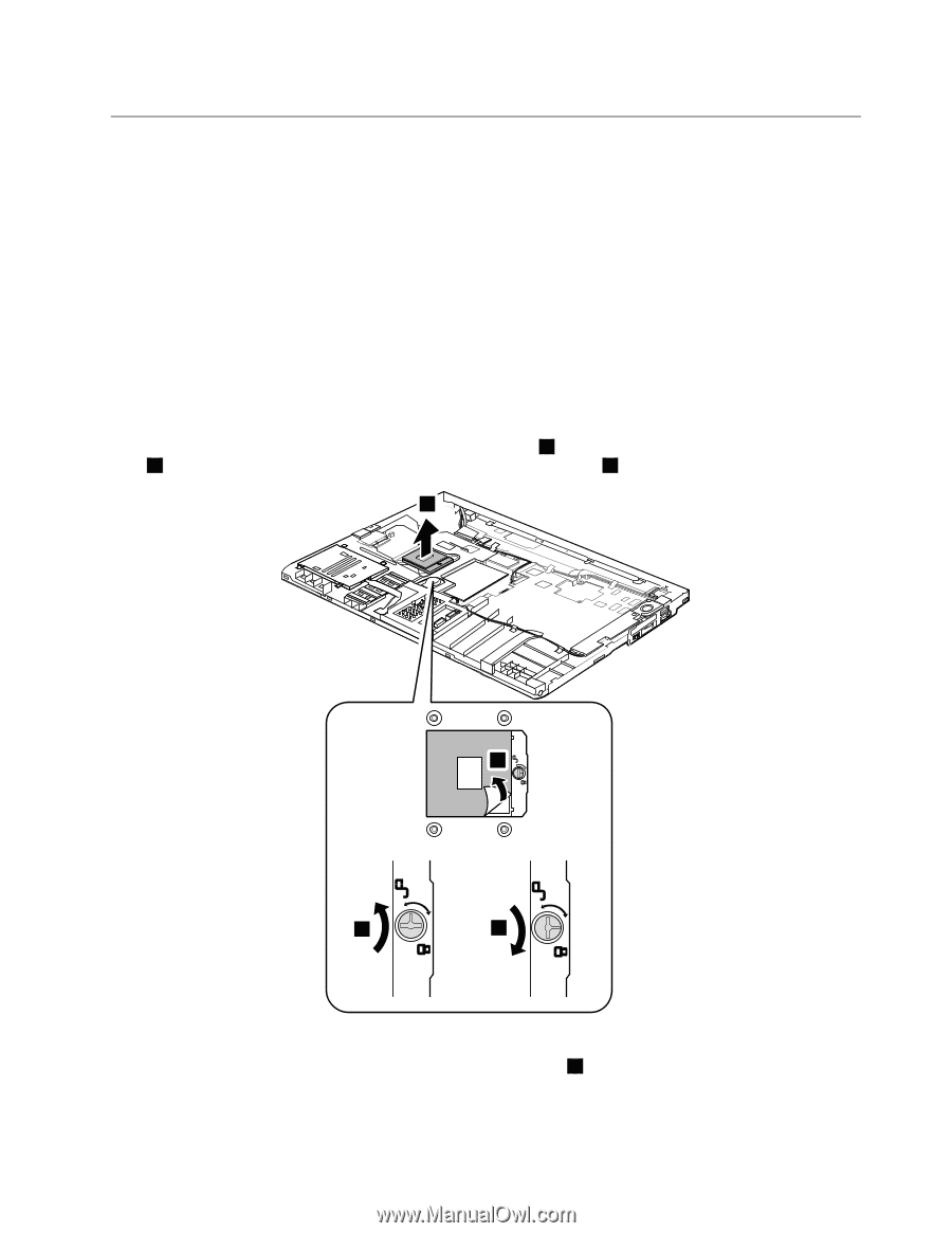
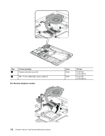
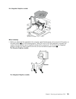
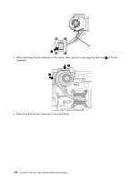
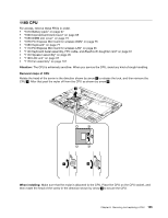
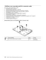
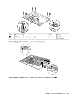
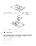
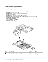
1180 CPU For access, remove these FRUs in order: • "1010 Battery pack" on page 67 • "1020 ExpressCard blank bezel" on page 68 • "1050 DIMM slot cover" on page 73 • "1070 PCI Express Mini Card for wireless WAN" on page 75 • "1080 Keyboard" on page 77 • "1110 PCI Express Mini Card for wireless LAN" on page 85 • "1120 Keyboard bezel assembly, FPC cable, and Bluethooth daughter card" on page 87 • "1150 Speaker assembly" on page 95 • "1160 LCD unit" on page 97 • "1170 Fan assembly" on page 101 Attention: The CPU is extremely sensitive. When you service the CPU, avoid any kind of rough handling. Removal steps of CPU Rotate the head of the screw in the direction shown by arrow 1 to release the lock, and then remove the CPU 2 . After that peel the mylar off from the CPU as shown by arrow 4 . 2 4 1 3 When installing: Make sure that the mylar is attached to the CPU. Place the CPU on the CPU socket, and then rotate the head of the screw in the direction shown by arrow 3 to secure the CPU. Chapter 8. Removing and replacing a FRU 105
-
 1
1 -
2
-
3
-
4
-
5
-
6
-
7
-
8
-
9
-
10
-
11
-
12
-
13
-
14
-
15
-
16
-
17
-
18
-
19
-
20
-
21
-
22
-
23
-
24
-
25
-
26
-
27
-
28
-
29
-
30
-
31
-
32
-
33
-
34
-
35
-
36
-
37
-
38
-
39
-
40
-
41
-
42
-
43
-
44
-
45
-
46
-
47
-
48
-
49
-
50
-
51
-
52
-
53
-
54
-
55
-
56
-
57
-
58
-
59
-
60
-
61
-
62
-
63
-
64
-
65
-
66
-
67
-
68
-
69
-
70
-
71
-
72
-
73
-
74
-
75
-
76
-
77
-
78
-
79
-
80
-
81
-
82
-
83
-
84
-
85
-
86
-
87
-
88
-
89
-
90
-
91
-
92
-
93
-
94
-
95
-
96
-
97
-
98
-
99
-
100
-
101
-
102
-
103
-
104
-
105
-
 106
106 -
 107
107 -
 108
108 -
 109
109 -
 110
110 -
 111
111 -
 112
112 -
 113
113 -
 114
114 -
 115
115 -
 116
116 -
117
-
118
-
119
-
120
-
121
-
122
-
123
-
124
-
125
-
126
-
127
-
128
-
129
-
130
-
131
-
132
-
133
-
134
-
135
-
136
-
137
-
138
-
139
-
140
-
141
-
142
-
143
-
144
-
145
-
146
-
147
-
148
-
149
-
150
-
151
-
152
-
153
-
154
-
155
-
156
-
157
-
158
-
159
-
160
-
161
-
162
-
163
-
164
-
165
-
166
-
167
-
168
-
169
-
170
-
171
-
172
-
173
-
174
-
175
-
176
-
177
-
178
-
179
-
180
-
181
-
182
-
183
-
184
-
185
-
186
 |
 |