Lenovo ThinkStation D10 User Manual - Page 125
Replacing a fan assembly, Install the new fan assembly, route the wiring, and then connect
 |
View all Lenovo ThinkStation D10 manuals
Add to My Manuals
Save this manual to your list of manuals |
Page 125 highlights
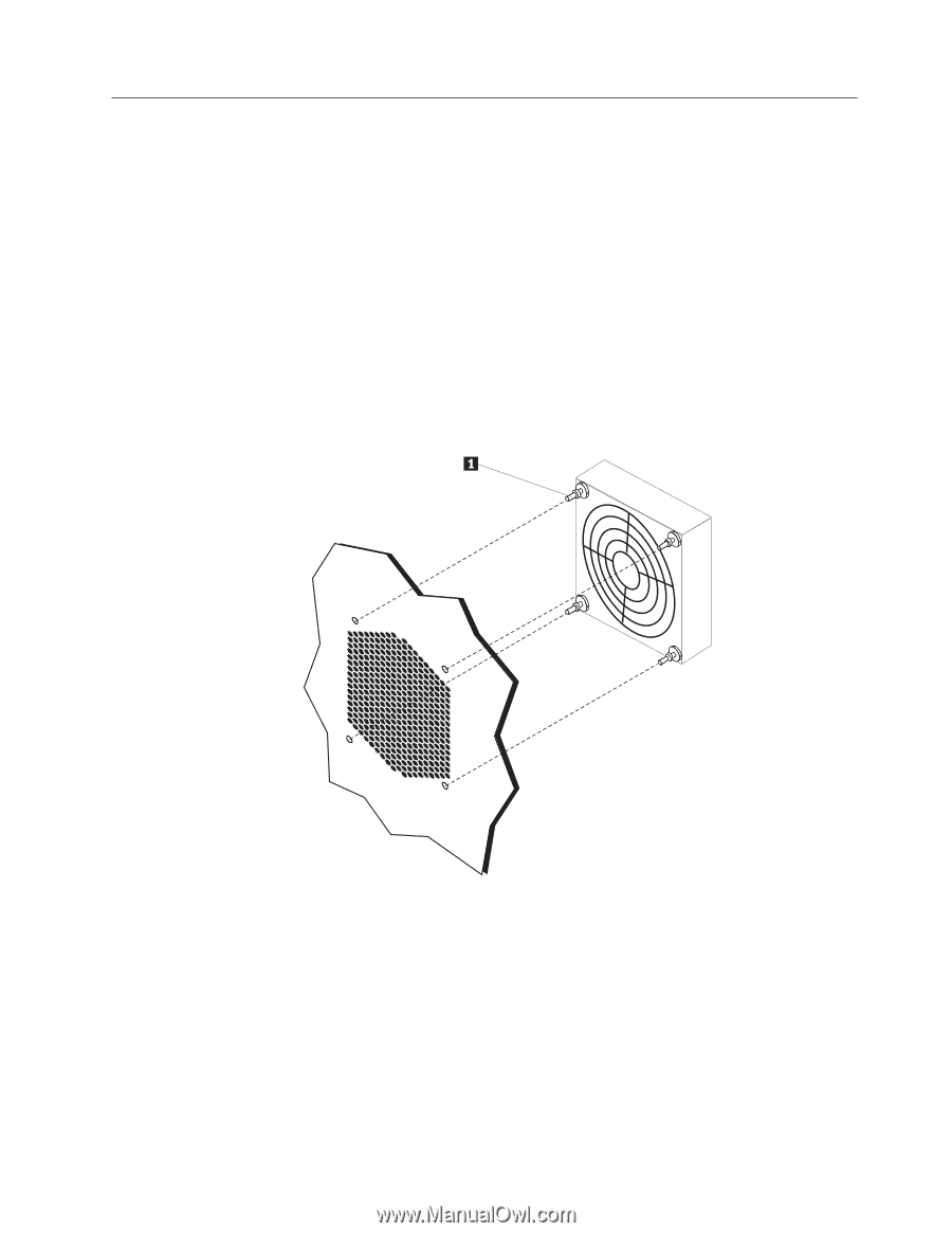
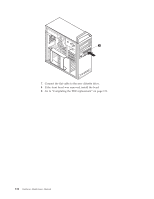
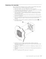
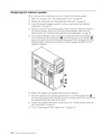
Replacing a fan assembly This section provides instructions on how to replace a fan assembly. Some models will have three fans. See "Internal components" on page 92. 1. Open the computer cover. See "Opening the cover" on page 94. 2. If necessary, remove the adapter cards to access the failing fan. See "Accessing system board components and drives" on page 96. 3. Note the routing of the fan-assembly wiring. See "System board connectors and components" on page 93. Disconnect the fan-assembly-wiring connector from the system board. 4. If you are replacing the front fan, remove the front bezel. See "Removing the front bezel" on page 95. 5. If you are replacing the hard disk drive fan, remove the fan bracket that holds the fan by using your fingers to release the fan bracket and then slide it outward 6. For all fans, remove the fan assembly by pulling the fan grommets 1 free of the bracket as shown. 7. Install the new fan assembly, route the wiring, and then connect the fan-wiring connector to the system board. See "System board connectors and components" on page 93. 8. Reinstall any adapters that were removed. See "Replacing an adapter card" on page 103. 9. Reinstall the front bezel if it was removed. See "Removing the front bezel" on page 95. 10. Go to "Completing the FRU replacement" on page 123. Chapter 9. Replacing FRUs (types 6423 and 6483) 119
-
 1
1 -
2
-
3
-
4
-
5
-
6
-
7
-
8
-
9
-
10
-
11
-
12
-
13
-
14
-
15
-
16
-
17
-
18
-
19
-
20
-
21
-
22
-
23
-
24
-
25
-
26
-
27
-
28
-
29
-
30
-
31
-
32
-
33
-
34
-
35
-
36
-
37
-
38
-
39
-
40
-
41
-
42
-
43
-
44
-
45
-
46
-
47
-
48
-
49
-
50
-
51
-
52
-
53
-
54
-
55
-
56
-
57
-
58
-
59
-
60
-
61
-
62
-
63
-
64
-
65
-
66
-
67
-
68
-
69
-
70
-
71
-
72
-
73
-
74
-
75
-
76
-
77
-
78
-
79
-
80
-
81
-
82
-
83
-
84
-
85
-
86
-
87
-
88
-
89
-
90
-
91
-
92
-
93
-
94
-
95
-
96
-
97
-
98
-
99
-
100
-
101
-
102
-
103
-
104
-
105
-
106
-
107
-
108
-
109
-
110
-
111
-
112
-
113
-
114
-
115
-
116
-
117
-
118
-
119
-
 120
120 -
 121
121 -
 122
122 -
 123
123 -
 124
124 -
 125
125 -
 126
126 -
 127
127 -
 128
128 -
 129
129 -
 130
130 -
131
-
132
-
133
-
134
-
135
-
136
-
137
-
138
-
139
-
140
-
141
-
142
-
143
-
144
-
145
-
146
-
147
-
148
-
149
-
150
-
151
-
152
-
153
-
154
-
155
-
156
-
157
-
158
-
159
-
160
-
161
-
162
-
163
-
164
-
165
-
166
-
167
-
168
-
169
-
170
-
171
-
172
-
173
-
174
-
175
-
176
-
177
-
178
-
179
-
180
-
181
-
182
-
183
-
184
-
185
-
186
-
187
-
188
-
189
-
190
-
191
-
192
-
193
-
194
-
195
-
196
-
197
-
198
-
199
-
200
-
201
-
202
-
203
-
204
-
205
-
206
-
207
-
208
-
209
-
210
-
211
-
212
-
213
-
214
-
215
-
216
-
217
-
218
-
219
-
220
-
221
-
222
-
223
-
224
-
225
-
226
-
227
-
228
-
229
-
230
-
231
-
232
-
233
-
234
-
235
-
236
-
237
-
238
-
239
-
240
-
241
-
242
-
243
-
244
-
245
-
246
-
247
-
248
 |
 |