Lenovo ThinkStation S30 Hardware Maintenance Manual - Page 118
Replacing the power supply assembly
 |
View all Lenovo ThinkStation S30 manuals
Add to My Manuals
Save this manual to your list of manuals |
Page 118 highlights
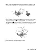
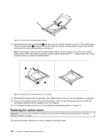
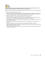
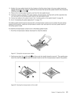
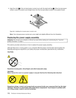
3. Align the notch 1 of the microprocessor socket cover with the alignment key 2 of the microprocessor socket. Lower the socket cover straight down into the microprocessor socket on the system board. Figure 49. Installing the microprocessor socket cover Note: Your microprocessor socket and cover might look slightly different from the illustration. Replacing the power supply assembly Attention: Do not open your computer or attempt any repair before reading and understanding the "Important Safety Information" on page 1. This section provides instructions on how to replace the power supply assembly. Although there are no moving parts in your computer after the power cord has been disconnected, the following warnings are required for your safety and proper Underwriters Laboratories (UL) certification. CAUTION: Hazardous moving parts. Keep fingers and other body parts away. CAUTION: Never remove the cover on a power supply or any part that has the following label attached. Hazardous voltage, current, and energy levels are present inside any component that has this label attached. There are no serviceable parts inside these components. If you suspect a problem with one of these parts, contact a service technician. 112 ThinkStation Hardware Maintenance Manual
-
 1
1 -
2
-
3
-
4
-
5
-
6
-
7
-
8
-
9
-
10
-
11
-
12
-
13
-
14
-
15
-
16
-
17
-
18
-
19
-
20
-
21
-
22
-
23
-
24
-
25
-
26
-
27
-
28
-
29
-
30
-
31
-
32
-
33
-
34
-
35
-
36
-
37
-
38
-
39
-
40
-
41
-
42
-
43
-
44
-
45
-
46
-
47
-
48
-
49
-
50
-
51
-
52
-
53
-
54
-
55
-
56
-
57
-
58
-
59
-
60
-
61
-
62
-
63
-
64
-
65
-
66
-
67
-
68
-
69
-
70
-
71
-
72
-
73
-
74
-
75
-
76
-
77
-
78
-
79
-
80
-
81
-
82
-
83
-
84
-
85
-
86
-
87
-
88
-
89
-
90
-
91
-
92
-
93
-
94
-
95
-
96
-
97
-
98
-
99
-
100
-
101
-
102
-
103
-
104
-
105
-
106
-
107
-
108
-
109
-
110
-
111
-
112
-
 113
113 -
 114
114 -
 115
115 -
 116
116 -
 117
117 -
 118
118 -
 119
119 -
 120
120 -
 121
121 -
 122
122 -
 123
123 -
124
-
125
-
126
-
127
-
128
-
129
-
130
-
131
-
132
 |
 |
