Lenovo Y70-70 Touch Hardware Maintenance Manual - Lenovo Y70-70 Touch - Page 46
LED board
 |
View all Lenovo Y70-70 Touch manuals
Add to My Manuals
Save this manual to your list of manuals |
Page 46 highlights
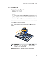
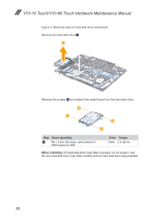
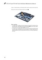
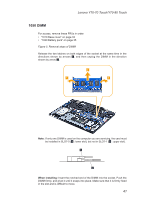
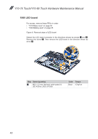
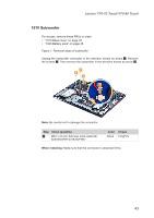
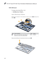
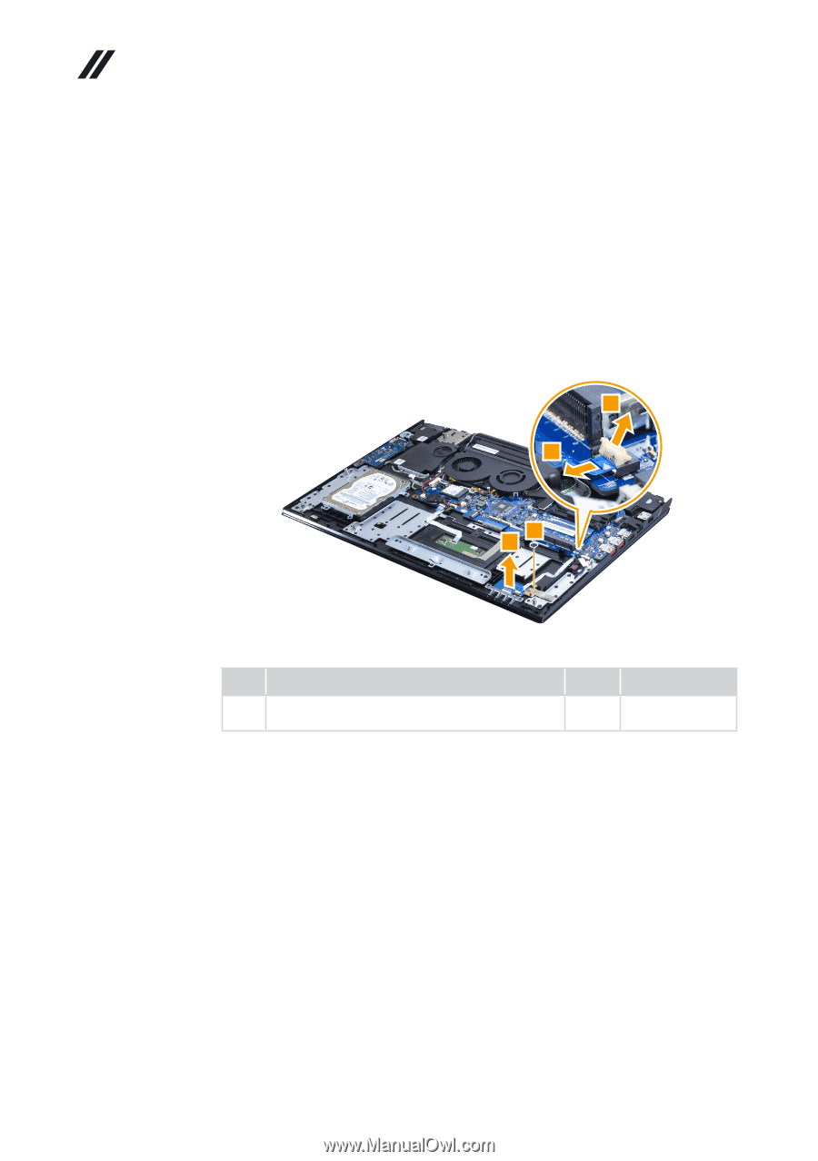
Y70-70 Touch/Y70-80 Touch Hardware Maintenance Manual 1060 LED board For access, remove these FRUs in order: • "1010 Base cover" on page 33 • "1020 Battery pack" on page 35 Figure 6. Removal steps of LED board Detach the LED board connector in the directions shown by arrows 1 and 2. Remove the screw 3. Then remove the LED board in the direction shown by arrow 4. 1 2 3 4 Step Screw (quantity) 3 M2.0 × 2.0 mm, flat-head, nylok-coated (1) LED PCB to LOGIC UP SUB Color Torque Black 1.5 kgf*cm 42
-
 1
1 -
2
-
3
-
4
-
5
-
6
-
7
-
8
-
9
-
10
-
11
-
12
-
13
-
14
-
15
-
16
-
17
-
18
-
19
-
20
-
21
-
22
-
23
-
24
-
25
-
26
-
27
-
28
-
29
-
30
-
31
-
32
-
33
-
34
-
35
-
36
-
37
-
38
-
39
-
40
-
 41
41 -
 42
42 -
 43
43 -
 44
44 -
 45
45 -
 46
46 -
 47
47 -
 48
48 -
 49
49 -
 50
50 -
 51
51 -
52
-
53
-
54
-
55
-
56
-
57
-
58
-
59
-
60
-
61
-
62
-
63
-
64
-
65
-
66
-
67
-
68
-
69
-
70
-
71
-
72
-
73
-
74
-
75
-
76
-
77
-
78
-
79
-
80
-
81
 |
 |
42
Y70-70 Touch/Y70-80 Touch Hardware Maintenance Manual
1060 LED board
For access, remove these FRUs in order:
•
“1010 Base cover” on page 33
•
“1020 Battery pack” on page 35
Figure 6. Removal steps of LED board
Detach the LED board connector in the directions shown by arrows
1
and
2
.
Remove the screw
3
. Then remove the LED board in the direction shown by
arrow
4
.
3
1
2
4
Step
Screw (quantity)
Color
Torque
3
M2.0 × 2.0 mm, flat-head, nylok-coated (1)
LED PCB to LOGIC UP SUB
Black
1.5 kgf*cm