Lenovo Y70-70 Touch Hardware Maintenance Manual - Lenovo Y70-70 Touch - Page 49
Fan assembly and Heat Sink assembly
 |
View all Lenovo Y70-70 Touch manuals
Add to My Manuals
Save this manual to your list of manuals |
Page 49 highlights
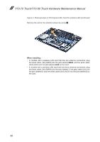
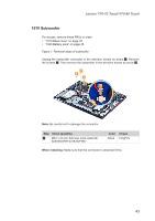
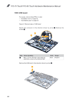
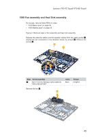
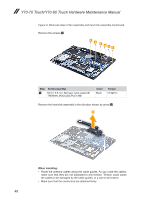
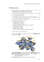
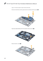
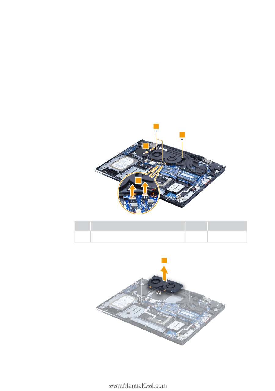
Lenovo Y70-70 Touch/Y70-80 Touch 1090 Fan assembly and Heat Sink assembly For access, remove these FRUs in order: • "1010 Base cover" on page 33 • "1020 Battery pack" on page 35 Figure 9. Removal steps of fan assembly and heat sink assembly Release the antenna cables and the speaker cables from the cable guides 1. Unplug the fan connectors in the direction shown by arrows 2. Remove the screws 3. 3 3 1 2 Step Screw (quantity) 3 M2.0 × 3.0 mm, flat-head, nylok-coated (3) FAN to KB SUP BKT Remove the fan 4. 4 Color Black Torque 2.0 kgf*cm 45
-
 1
1 -
2
-
3
-
4
-
5
-
6
-
7
-
8
-
9
-
10
-
11
-
12
-
13
-
14
-
15
-
16
-
17
-
18
-
19
-
20
-
21
-
22
-
23
-
24
-
25
-
26
-
27
-
28
-
29
-
30
-
31
-
32
-
33
-
34
-
35
-
36
-
37
-
38
-
39
-
40
-
41
-
42
-
43
-
 44
44 -
 45
45 -
 46
46 -
 47
47 -
 48
48 -
 49
49 -
 50
50 -
 51
51 -
 52
52 -
 53
53 -
 54
54 -
55
-
56
-
57
-
58
-
59
-
60
-
61
-
62
-
63
-
64
-
65
-
66
-
67
-
68
-
69
-
70
-
71
-
72
-
73
-
74
-
75
-
76
-
77
-
78
-
79
-
80
-
81
 |
 |
45
Lenovo Y70-70 Touch/Y70-80 Touch
1090
Fan assembly and Heat Sink assembly
For access, remove these FRUs in order:
•
“1010 Base cover” on page 33
•
“1020 Battery pack” on page 35
Figure 9. Removal steps of fan assembly and heat sink assembly
Release the antenna cables and the speaker cables from the cable guides
1
.
Unplug the fan connectors in the direction shown by arrows
2
. Remove the
screws
3
.
1
3
3
2
Step
Screw (quantity)
Color
Torque
3
M2.0 × 3.0 mm, flat-head, nylok-coated (3)
FAN to KB SUP BKT
Black
2.0 kgf*cm
Remove the fan
4
.
4