Lenovo Y70-70 Touch Hardware Maintenance Manual - Lenovo Y70-70 Touch - Page 50
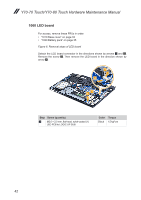
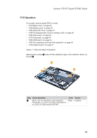
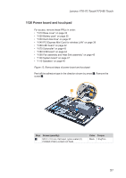
Screw quantity, Color, Torque
 |
View all Lenovo Y70-70 Touch manuals
Add to My Manuals
Save this manual to your list of manuals |
Page 50 highlights
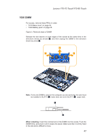
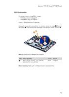
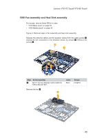
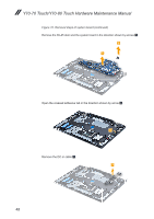
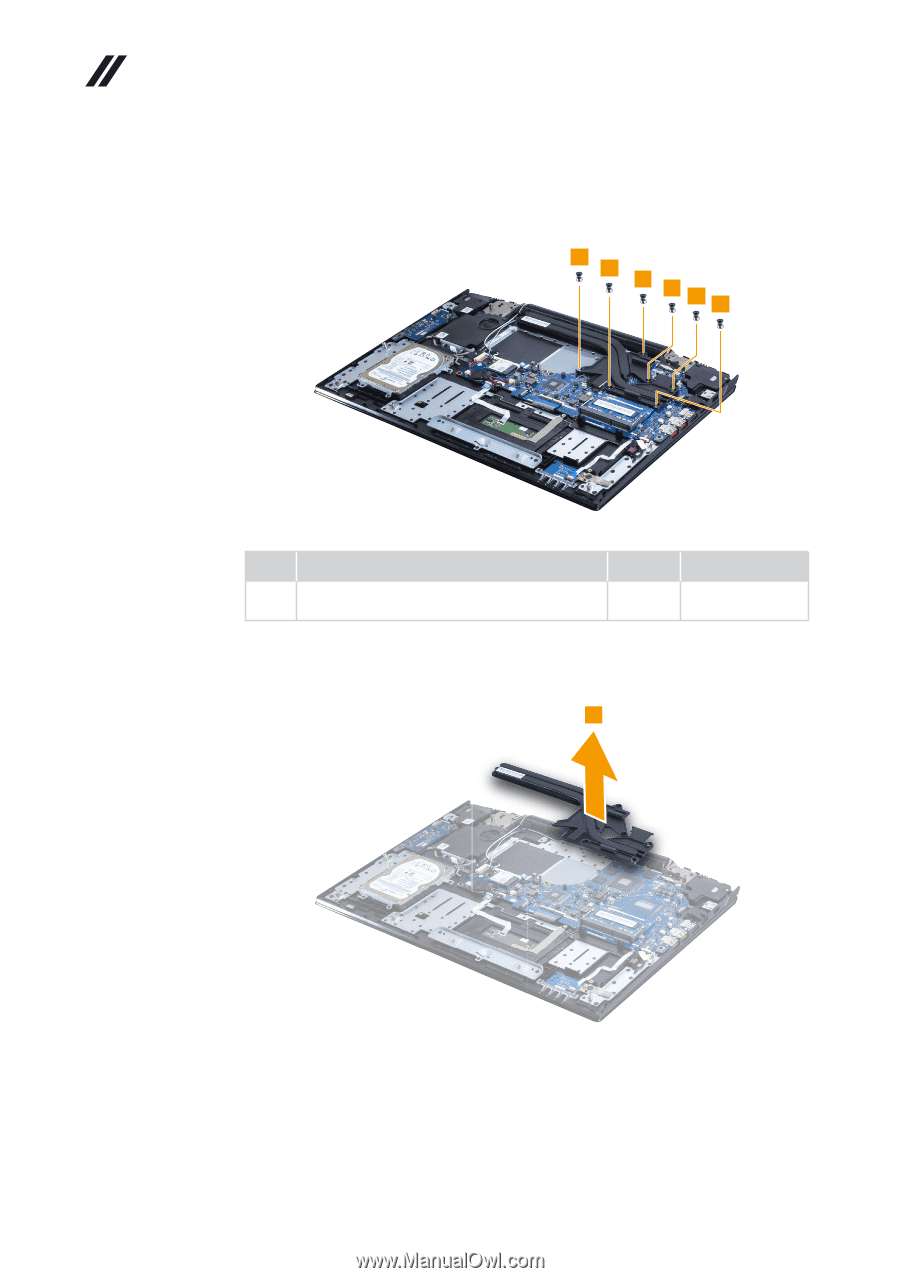
Y70-70 Touch/Y70-80 Touch Hardware Maintenance Manual Figure 9. Removal steps of fan assembly and heat sink assembly (continued) Remove the screws 5. 5 5 5 555 Step Screw (quantity) 5 M2.0 × 6.5 mm, flat-head, nylok-coated (6) THERMAL MODULE(CPU) to MB Color Black Torque 2.5 kgf*cm Remove the heat sink assembly in the direction shown by arrow 6. 6 When installing: • Route the antenna cables along the cable guides. As you route the cables, make sure that they are not subjected to any tension. Tension could cause the cables to be damaged by the cable guides, or a wire to be broken. • Make sure that the connectors are attached firmly. 46
-
 1
1 -
2
-
3
-
4
-
5
-
6
-
7
-
8
-
9
-
10
-
11
-
12
-
13
-
14
-
15
-
16
-
17
-
18
-
19
-
20
-
21
-
22
-
23
-
24
-
25
-
26
-
27
-
28
-
29
-
30
-
31
-
32
-
33
-
34
-
35
-
36
-
37
-
38
-
39
-
40
-
41
-
42
-
43
-
44
-
 45
45 -
 46
46 -
 47
47 -
 48
48 -
 49
49 -
 50
50 -
 51
51 -
 52
52 -
 53
53 -
 54
54 -
 55
55 -
56
-
57
-
58
-
59
-
60
-
61
-
62
-
63
-
64
-
65
-
66
-
67
-
68
-
69
-
70
-
71
-
72
-
73
-
74
-
75
-
76
-
77
-
78
-
79
-
80
-
81
 |
 |
46
Y70-70 Touch/Y70-80 Touch Hardware Maintenance Manual
Figure 9. Removal steps of fan assembly and heat sink assembly (continued)
Remove the screws
5
.
5
5
5
5
5
5
Step
Screw (quantity)
Color
Torque
5
M2.0 × 6.5 mm, flat-head, nylok-coated (6)
THERMAL MODULE(CPU) to MB
Black
2.5 kgf*cm
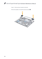
Remove the heat sink assembly in the direction shown by arrow
6
.
6
When installing:
•
Route the antenna cables along the cable guides. As you route the cables,
make sure that they are not subjected to any tension. Tension could cause
the cables to be damaged by the cable guides, or a wire to be broken.
•
Make sure that the connectors are attached firmly.