Lenovo Yoga 2 11 Hardware Maintenance Manual - Lenovo Yoga 2 11 - Page 42
PCI Express Mini Card for wireless LAN, Notes, When installing
 |
View all Lenovo Yoga 2 11 manuals
Add to My Manuals
Save this manual to your list of manuals |
Page 42 highlights
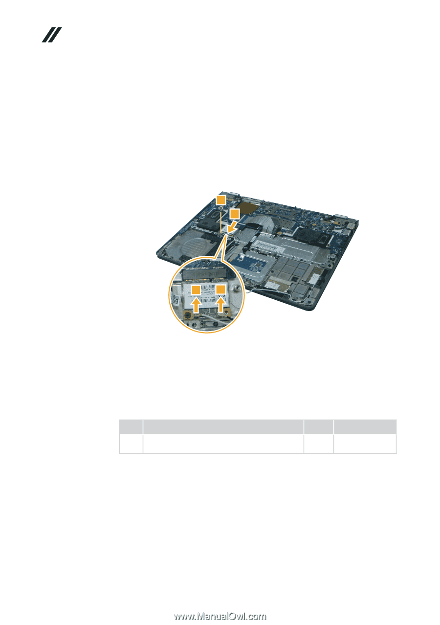
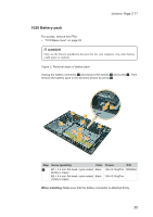
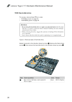
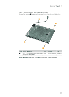
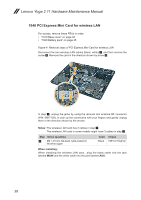
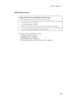
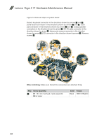
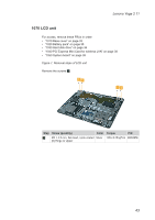
Lenovo Yoga 2 11 Hardware Maintenance Manual 1040 PCI Express Mini Card for wireless LAN For access, remove these FRUs in order: • "1010 Base cover" on page 33 • "1020 Battery pack" on page 35 Figure 4. Removal steps of PCI Express Mini Card for wireless LAN Disconnect the two wireless LAN cables (black, white) 1, and then remove the screw 2. Remove the card in the direction shown by arrow 3. 2 3 1 1 In step 1, unplug the jacks by using the removal tool antenna RF connector (P/N: 08K7159), or pick up the connectors with your fingers and gently unplug them in the direction shown by the arrows. Notes: The wireless LAN card has 2 cables in step 1. The wireless LAN card in some models might have 3 cables in step 1. Step Screw (quantity) 2 M2 × 3.5 mm, flat-head, nylok-coated (1) WLAN to Upper Color Torque Black 1.85+/-0.15 kgf*cm When installing: When installing the wireless LAN card, plug the black cable into the jack labeled MAIN and the white cable into the jack labeled AUX. 38
-
 1
1 -
2
-
3
-
4
-
5
-
6
-
7
-
8
-
9
-
10
-
11
-
12
-
13
-
14
-
15
-
16
-
17
-
18
-
19
-
20
-
21
-
22
-
23
-
24
-
25
-
26
-
27
-
28
-
29
-
30
-
31
-
32
-
33
-
34
-
35
-
36
-
 37
37 -
 38
38 -
 39
39 -
 40
40 -
 41
41 -
 42
42 -
 43
43 -
 44
44 -
 45
45 -
 46
46 -
 47
47 -
48
-
49
-
50
-
51
-
52
-
53
-
54
-
55
-
56
-
57
-
58
-
59
-
60
-
61
-
62
-
63
-
64
-
65
-
66
-
67
-
68
-
69
-
70
-
71
-
72
-
73
-
74
-
75
-
76
 |
 |