Lenovo Yoga 2 11 Hardware Maintenance Manual - Lenovo Yoga 2 11 - Page 56
Removal steps of LCD module continued
 |
View all Lenovo Yoga 2 11 manuals
Add to My Manuals
Save this manual to your list of manuals |
Page 56 highlights
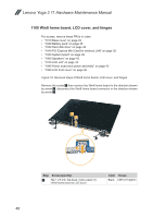
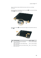
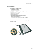
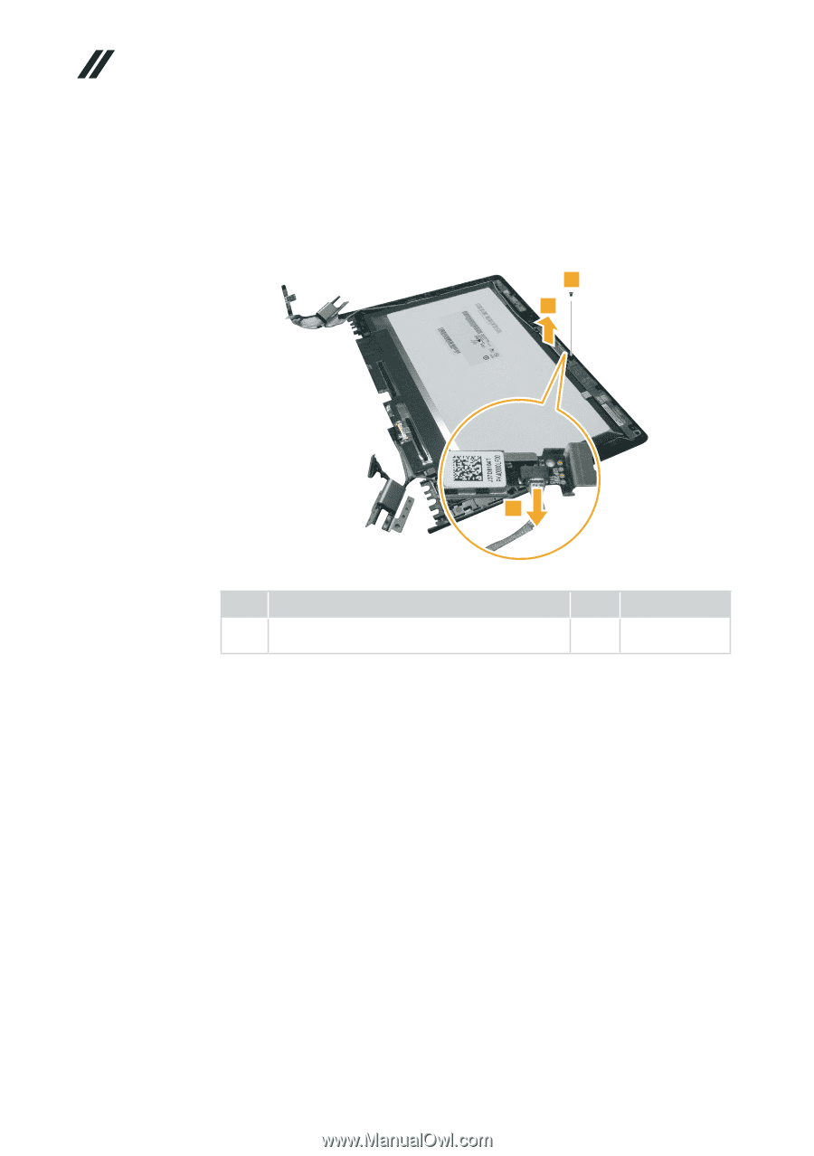
Lenovo Yoga 2 11 Hardware Maintenance Manual Figure 11. Removal steps of LCD module (continued) Remove the screw 3. Lift the camera and the camera bracket slightly 4. Unplug the integrated camera connector in the direction shown by arrow 5. Remove the integrated camera bracket and integrated camera from the LCD module. 3 4 5 Step Screw (quantity) 3 M1.6 × 2.5 mm, flat-head, nylok-coated (1) Camera to LCD cover Color Torque Black 1.00+/-0.20 kgf*cm 52
-
 1
1 -
2
-
3
-
4
-
5
-
6
-
7
-
8
-
9
-
10
-
11
-
12
-
13
-
14
-
15
-
16
-
17
-
18
-
19
-
20
-
21
-
22
-
23
-
24
-
25
-
26
-
27
-
28
-
29
-
30
-
31
-
32
-
33
-
34
-
35
-
36
-
37
-
38
-
39
-
40
-
41
-
42
-
43
-
44
-
45
-
46
-
47
-
48
-
49
-
50
-
 51
51 -
 52
52 -
 53
53 -
 54
54 -
 55
55 -
 56
56 -
 57
57 -
 58
58 -
 59
59 -
 60
60 -
 61
61 -
62
-
63
-
64
-
65
-
66
-
67
-
68
-
69
-
70
-
71
-
72
-
73
-
74
-
75
-
76
 |
 |
52
Lenovo Yoga 2 11 Hardware Maintenance Manual
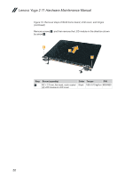
Figure 11. Removal steps of LCD module (continued)
Remove the screw
3
. Lift the camera and the camera bracket slightly
4
.
Unplug the integrated camera connector in the direction shown by arrow
5
.
Remove the integrated camera bracket and integrated camera from the LCD
module.
3
5
4
Step
Screw (quantity)
Color
Torque
3
M1.6 × 2.5 mm, flat-head, nylok-coated (1)
Camera to LCD cover
Black
1.00+/-0.20 kgf*cm