Lexmark E250D Service Manual - Page 71
Black Heavy background, PC Kit not a FRU
 |
View all Lexmark E250D manuals
Add to My Manuals
Save this manual to your list of manuals |
Page 71 highlights
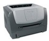
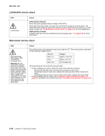
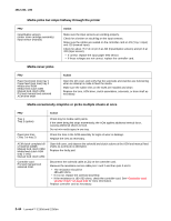
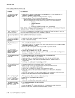
4512-220, -230 Black page Note: Incorrect laser exposure or incorrect charging of the photoconductor causes an all black page. Always verify the same results from a different toner cartridge assembly and developer before proceeding. FRU Toner electrodes (not a FRU) LVPS/HVPS board Controller card Miscellaneous cables Action Check the three rearward electrodes below the toner cartridge assembly for contamination or damage. Correct as necessary. Check continuity between the cable (DEV, TAR, and doctor blade) connection PCN3 and on the contact tips below the toner cartridge assembly. • If continuity fails, call the next level of service. With the printer off, disconnect the LVPS/HVPS cable from J19 on the controller card. Turn the printer on, and verify +24 V dc on pins 8 and 9 of the cable. Verify ground on pins 7, 12, and 14. • If the voltage is incorrect, replace LVPS/HVPS board. • If grounds are incorrect, check ground paths. • Check confinuity in the cable. Replace the cable if necessary. • If voltage is correct and the toner electrodes are good, replace the controller card. • See the "LVPS/HVPS service check" on page 2-42 and the "Controller card service check" on page 2-39, if necessary. Heavy background Poor development or poorly charged toner particles cause excessive background. This is more noticeable as the toner cartridge nears end-of-life. FRU Toner cartridge (not a FRU) PC Kit (not a FRU) LVPS/HVPS Controller card Action Check the toner darkness setting in the driver. Try a lower setting. Make sure the toner cartridge and PC Kit are correctly installed and the high voltage contacts are clean. If the toner cartridge and PC Kit are installed correctly, try a new PC Kit first and then toner cartridge. Check the contacts for correct installation and contamination where contact is made between the toner cartridge assembly and spring contacts which connect to the LVPS/ HVPS board at PCN3. Clean as necessary. If this does not correct the problem, replace the following FRUs one at a time in the order shown: • LVPS/HVPS board (See "Black page" on page 3-47 for pin values.) • Controller card Diagnostic information 2-47
-
 1
1 -
2
-
3
-
4
-
5
-
6
-
7
-
8
-
9
-
10
-
11
-
12
-
13
-
14
-
15
-
16
-
17
-
18
-
19
-
20
-
21
-
22
-
23
-
24
-
25
-
26
-
27
-
28
-
29
-
30
-
31
-
32
-
33
-
34
-
35
-
36
-
37
-
38
-
39
-
40
-
41
-
42
-
43
-
44
-
45
-
46
-
47
-
48
-
49
-
50
-
51
-
52
-
53
-
54
-
55
-
56
-
57
-
58
-
59
-
60
-
61
-
62
-
63
-
64
-
65
-
 66
66 -
 67
67 -
 68
68 -
 69
69 -
 70
70 -
 71
71 -
 72
72 -
 73
73 -
 74
74 -
 75
75 -
 76
76 -
77
-
78
-
79
-
80
-
81
-
82
-
83
-
84
-
85
-
86
-
87
-
88
-
89
-
90
-
91
-
92
-
93
-
94
-
95
-
96
-
97
-
98
-
99
-
100
-
101
-
102
-
103
-
104
-
105
-
106
-
107
-
108
-
109
-
110
-
111
-
112
-
113
-
114
-
115
-
116
-
117
-
118
-
119
-
120
-
121
-
122
-
123
-
124
-
125
-
126
-
127
-
128
-
129
-
130
-
131
-
132
-
133
-
134
-
135
-
136
-
137
-
138
-
139
-
140
-
141
-
142
-
143
-
144
-
145
-
146
-
147
-
148
-
149
-
150
-
151
-
152
-
153
-
154
-
155
-
156
-
157
-
158
-
159
-
160
-
161
-
162
-
163
-
164
 |
 |