Lexmark E352DN Service Manual
Lexmark E352DN - E 352dn B/W Laser Printer Manual
 |
View all Lexmark E352DN manuals
Add to My Manuals
Save this manual to your list of manuals |
Lexmark E352DN manual content summary:
- Lexmark E352DN | Service Manual - Page 1
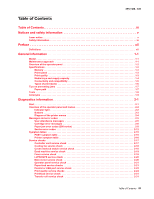
Edition: May 15, 2007 Lexmark™ E350d, E352dn 4512-420 4512-430 • Table of contents • Start diagnostics • Safety and notices • Trademarks • Index Lexmark and Lexmark with diamond design are trademarks of Lexmark International, Inc., registered in the United States and/or other countries. - Lexmark E352DN | Service Manual - Page 2
.com. Lexmark may use or distribute any of the information you supply in any way it believes appropriate without incurring any obligation to you. References in this publication to products, programs, or services do not imply that the manufacturer intends to make these available in all countries - Lexmark E352DN | Service Manual - Page 3
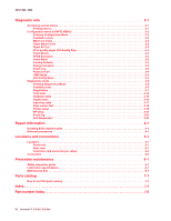
2-19 Fuser service check 2-19 LVPS/HVPS service check 2-20 Main motor service check 2-20 Operator panel service check 2-21 Paper feed service checks 2-21 Parallel or USB port service check 2-23 Print quality service checks 2-24 Printhead service check 2-31 Transfer roll service check 2-31 - Lexmark E352DN | Service Manual - Page 4
Rear view 5-1 Controller card connector pin values 5-2 Connectors 5-4 Preventive maintenance 6-1 Safety inspection guide 6-1 Lubrication specifications 6-1 Maintenance kits 6-1 Parts catalog 7-1 How to use this parts catalog 7-1 Index I-1 Part number index I-5 iv Lexmark™ E350d, E352dn - Lexmark E352DN | Service Manual - Page 5
in the wavelength region of 770-795 nanometers. The laser system and printer are designed so there is never any human access to laser radiation above a Class I level during normal operation, user maintenance, or prescribed service condition. Laser Der Drucker erfüllt gemäß amtlicher Bestätigung der - Lexmark E352DN | Service Manual - Page 6
galliumarsenid laser, som arbejder på bølgelængdeområdet 770-795 nanometer. Lasersystemet og printeren er udformet således, at mennesker aldrig udsættes for en laserstråling over Klasse I-niveau ved normal drift, brugervedligeholdelse eller obligatoriske servicebetingelser. vi Lexmark™ E350d, E352dn - Lexmark E352DN | Service Manual - Page 7
del är öppnad och spärren är urkopplad. Betrakta ej strålen. Laser-notis Denna skrivare är i USA certifierad att motsvara kraven i ndning, underhåll som utförs av användaren eller annan föreskriven serviceåtgärd. Laser-melding Skriveren er godkjent i USA etter kravene i DHHS 21 CFR, underkapittel - Lexmark E352DN | Service Manual - Page 8
4512-420, -430 viii Lexmark™ E350d, E352dn - Lexmark E352DN | Service Manual - Page 9
and approvals of the original design and specific components. The manufacturer is not responsible for safety in the event of use of unauthorized replacement parts. • The maintenance information for this product has been prepared for use by a professional service person and is not intended to be - Lexmark E352DN | Service Manual - Page 10
peligro y tomar las precauciones necesarias. • PRECAUCIÓN: este símbolo indica que el voltaje de la parte del equipo con la que está trabajando es peligroso. Antes de empezar, desenchufe el equipo de estar ligado à corrente eléctrica para realizar a tarefa necessária. x Lexmark™ E350d, E352dn - Lexmark E352DN | Service Manual - Page 11
producte. El personal professional ha d'estar-ne assabentat i prendre les mesures convenients. • PRECAUCIÓ: aquest símbol indica que el voltatge de la part de l'equip amb la qual esteu treballant és perillós. Abans de començar, desendolleu l'equip o extremeu les precaucions si, per treballar - Lexmark E352DN | Service Manual - Page 12
locations and test points on the printer. 6. Preventive maintenance contains the lubrication specifications and recommendations to prevent problems. 7. Parts catalog contains illustrations and part numbers for individual FRUs. Appendix A contains service tips and information. Appendix B contains - Lexmark E352DN | Service Manual - Page 13
support via USB and/or parallel ports, and prints 35 pages per minute on letter-size media (34 ppm on A4, 29 ppm on legal). Maintenance approach The diagnostic information in this manual leads to the correct field replaceable unit (FRU) or part. Use the error code charts, symptom index, and service - Lexmark E352DN | Service Manual - Page 14
Right Menu ), Back , and Go A label located on the inside front door shows the operator panel buttons. An additional translated label is included in the printer box. 1-2 Lexmark™ E350d, E352dn - Lexmark E352DN | Service Manual - Page 15
cards (DBCS) Print speed 4512-420 Lexmark E350d 32MB n/a 160MB ✔ ✔ 4512-430 Lexmark E352dn 32MB n/a 160MB ✔ ✔ Media Size 4512-420 Lexmark E350d Letter-8.5 x 11 in. 35 ppm A4-210 x 297 mm 34 ppm Legal-8.5 x 14 in. 29ppm Speed measured on media from tray 1, simplex, and at 600 x 600 dpi - Lexmark E352DN | Service Manual - Page 16
trays and supply capacity Item 4512-420 Lexmark E350d Available input trays 250-sheet tray ✔ 550-sheet option drawer ✔ 550-sheet tray ✔ Dust cover ✔ Toner and photoconductor Toner cartridge 1,500 standard pages SWE¹ 3,500 standard pages SWE¹ High toner cartridge Photoconductor kit - Lexmark E352DN | Service Manual - Page 17
(10/100 Base TX) n/a ✔ Optional local connections External print server support ✔ ✔ Option slots Memory slots (100-pin DIMM) 1 1 Flash memory / option card 2 2 * The E 350d and E352dn products are USB 2.0 certified devices supporting hi-speed (480MB/sec.) data transfer. General - Lexmark E352DN | Service Manual - Page 18
(16-24 lb) • 550 paper • 50 tables** • 50 transparencies Manual feeder A4, A5, A6 (grain long only), JIS B5, letter, legal, executive, folio, statement, Universal¹ 7 3/4, 9, 10, DL, C5, B5 Plain paper, 60-163 g/m² 1 transparencies, paper labels (single- (16-43 lb) sided only) Card stock - Lexmark E352DN | Service Manual - Page 19
jams Paper path 4512-420, -430 *Measurements are approximate paper lengths (millimeters) **Sensors are measured at rotation/position which they are tripped A Paper path B Manual feed sensor C Upper end feed rolls D Input sensor E Transfer roll F Fuser G Fuser exit rolls H Fuser - Lexmark E352DN | Service Manual - Page 20
tray before pushing the tray into the printer. • Make sure paper guides are positioned before loading the paper or specialty media. • Do not remove trays while a job is printing. • Before loading Card Stock & Label Guide available on the Lexmark Web site at www.lexmark.com for more information about - Lexmark E352DN | Service Manual - Page 21
(or paper feed) Analog-to-digital Converter Application Specific Integrated Circuit Complete Bill Of Material Development Roll (of print cartridge/photoconductor system) Dual In-Line Memory Module External Network Adapter Field Replaceable Unit Host Based Printing High Voltage Power Supply Liquid - Lexmark E352DN | Service Manual - Page 22
4512-420, -430 1-10 Lexmark™ E350d, E352dn - Lexmark E352DN | Service Manual - Page 23
Busy is displayed. 6. Close Door will be displayed if the cover is open. 7. Any cartridge errors, such as Defective Cartridge, are displayed. 8. Applicable maintenance messages are displayed. 9. Applicable toner low messages are displayed. 10. The printer displays Ready. Diagnostics information 2-1 - Lexmark E352DN | Service Manual - Page 24
4512-420, -430 Overview of the operator panel and menus Indicator light The indicator light gives information about the status of the printer. If the light is Off On Blinking The printer is Off On, but idle On and busy 2-2 Lexmark™ E350d, E352dn - Lexmark E352DN | Service Manual - Page 25
Source is displayed, then opens the item and displays the default setting. If a menu item such as Manual Feeder is displayed, then saves the selection as the new default setting for Paper Source. The printer will display the Saved message momentarily and then return to the menu item level. Press and - Lexmark E352DN | Service Manual - Page 26
Fonts Print Demo Factory Defaults Hex Trace Setup Menu Eco-Mode Quiet Mode Printer Language Power Saver Resource Save Print Timeout Wait Timeout Auto Continue Jam Recovery Page Protect Print area Display Language Toner Alarm Job Menu Reset Printer Quality Menu Print Resolution Toner Darkness Small - Lexmark E352DN | Service Manual - Page 27
: The network code can be downloaded while this message is displayed. Load manual feeder with Load manual feeder with Load manual feeder with Load manual feeder with • Load the specified media in the manual feed tray or multipurpose feeder. • To - Lexmark E352DN | Service Manual - Page 28
Engine Code DO NOT POWER OFF Program Flash DO NOT POWER OFF • Load the input source with the correct type and size media. • Cancel the current job. Replace the maintenance items and, if necessary, reset the printer maintenance counter. The printer menus are disabled. The printer settings cannot be - Lexmark E352DN | Service Manual - Page 29
) Message Prog System Code DO NOT POWER OFF Ready Remove Paper Standard Bin Resetting Maint Cnt Valu Resetting PC Cnt Value Resetting the Printer Res Reduced Restoring Factory Defaults Std Bin Full Toner Low Tray Missing USM Waiting Action The printer is programming new system code. Wait - Lexmark E352DN | Service Manual - Page 30
of the specified length. Paper jam error codes (200-series) Error Description 200.00 Paper jam around input sensor. 200.01 Classic input jam. The media is too long over the input sensor. Possible causes include multi-sheet feed, tray size sensing problem, and media slippage. 200.02 The main input - Lexmark E352DN | Service Manual - Page 31
4512-420, -430 Paper jam error codes (200-series) (Continued) Error Description 200.20 The media is too long over the manual feeder sensor. Possible causes include multi-sheet feed, media size (length) problem, pre-staged media in the tray. 200.22 FAILED SMALL GAP OR NO GAP JAM RECOVERY. Engine - Lexmark E352DN | Service Manual - Page 32
to open the gap by stopping the feed rolls, trailing edge was seen at the input sensor, manual feeder sensor is no longer covered. 241.19 Second pick attempted failed from Tray 1, no pages printed since calling a 241.10 or a prior 241.19. 242.00 Paper jam near tray 2. 2-10 Lexmark™ E350d, E352dn - Lexmark E352DN | Service Manual - Page 33
4512-420, -430 Paper jam error codes (200-series) (Continued) Error Description 242.01 Took too long to ramp up dc feed motor 242.08 Received lots of dc feed interrupts before losing them 242.10 Second pick attempt failed from Tray 2 242.12 Second pick from manual feeder, tray 1, or feeder failed - Lexmark E352DN | Service Manual - Page 34
the printer can be put into POR to temporarily recover from the error condition. Service error codes (9xx) Error Description Engine software service errors 902.xx Engine software error Transfer service errors 917.00 Transfer service error 917.01 Transfer servo result too low. Fuser service errors - Lexmark E352DN | Service Manual - Page 35
speed control is at maximum in fan control adjustment state. Printhead service errors 931.00 No first hsync 931.01 No first hsync 932.00 Lost hsyncs 932.01 Lost hsyncs 933.00 Printhead boost signal failure 935.10 Printhead sweep error, swept through Hz range without finding the resonant frequency - Lexmark E352DN | Service Manual - Page 36
during position control 937.03 Overspeed detected during speed control Power supply service errors 940.00 LVPS service error 940.01 Line frequency outside allowed range of 45Hz-64Hz 940.02 Line frequency below 43Hz 940.03 No zero cross detected on belt fuser model 2-14 Lexmark™ E350d, E352dn - Lexmark E352DN | Service Manual - Page 37
check" on page 2-18. See "Fuser service check" on page 2-19. See "Fuser service check" on page 2-19. See "Paper feed service checks" on page 2-21. Note: Investigate any displayed codes before proceeding with these symptoms. For example, a missing toner cartridge will prevent POST from completing - Lexmark E352DN | Service Manual - Page 38
fan not working. Fuser parts melted. Toner not fused to the media. Paper jams. Main motor noisy or not moving. Media skew. Printer not communicating with " on page 2-23. See "Dead machine service check" on page 2-19. See "Solving print quality problems" on page 3-28. 2-16 Lexmark™ E350d, E352dn - Lexmark E352DN | Service Manual - Page 39
4512-420, -430 Service checks Service checks which involve measuring voltages on the LVPS/HVPS (low voltage power supply/ high voltage power supply board) should be performed with the printer positioned on its back side. Note: When making voltage readings, always use frame ground unless another - Lexmark E352DN | Service Manual - Page 40
interlock switch. • If both pass continuity, turn the printer on, and measure +5 V dc on pin 2 at J6 on the controller card. • Verify pin 3 at J6 is ground. • If voltage or ground is not present, see "Controller card service check" on page 2-17 for more information. 2-18 Lexmark™ E350d, E352dn - Lexmark E352DN | Service Manual - Page 41
127 V ac for the 110 V model printer • 200 V ac-240 V ac for the 220 V model printer This printer uses a belt fuser and therefore does not have a lamp. Fuser service check FRU Fuser power cable LVPS/HVPS Fuser Fuser Action Unplug the printer, and disconnect the fuser cable plug from the LVPS/HVPS - Lexmark E352DN | Service Manual - Page 42
the motor. - If continuity does not exist on one or more of the wires, replace the motor cable. • If these voltages are not correct, see "Controller card connector pin values" on page 5-2, or replace the controller card. See "Controller card removal" on page 4-13. 2-20 Lexmark™ E350d, E352dn - Lexmark E352DN | Service Manual - Page 43
page 3-17. Buttons If the buttons do not respond, replace the operator panel. There is no test or repair for the faulty switches. Paper feed service checks Paper jam error indication during POST FRU Fuser (exit sensor) Input/duplex sensor Manual feed sensor Action If the exit sensor flag, which - Lexmark E352DN | Service Manual - Page 44
3 and 4. • The resistance should be 180-250 ohms. • If it is not, replace the solenoid assembly. • If the resistance is 180-250 ohms, check the controller card. See "Controller card service check" on page 2-17 for more information. Replace controller card as necessary. 2-22 Lexmark™ E350d, E352dn - Lexmark E352DN | Service Manual - Page 45
each on its hub. Check side guides on Tray 1 and Tray 2. Guides set for a full stack of media may be too wide when the stack is short. Media "trees," wrinkles, stacks poorly, or curls FRU Fuser Action This problem is most likely due to a worn backup roll. It causes the printer to run hotter than - Lexmark E352DN | Service Manual - Page 46
transfer roll gear. • If there is not continuity, call the next level of service. Try a different toner cartridge and PC kit. • If those fail, replace the LVPS/HVPS, controller card, or the printhead in that order. Also, see "Solving print quality problems" on page 3-28. 2-24 Lexmark™ E350d, E352dn - Lexmark E352DN | Service Manual - Page 47
new PC Kit first and then toner cartridge. Check the contacts for correct installation and contamination where contact is made between the print cartridge assembly and spring contacts which connect to the LVPS/HVPS board at PCN3. Clean as necessary. If this does not correct the problem, replace the - Lexmark E352DN | Service Manual - Page 48
(photoconductor) drum. Try a new PC Kit. Note: Do not touch the transfer roll except at its ends. Place a sheet of paper over the roll to prevent damage from finger oils or hand lotion. Check the springs in the left and right transfer roll bearings. The bearing assemblies should support the transfer - Lexmark E352DN | Service Manual - Page 49
. With the printer off, check to make sure that the laser beam is not blocked. Inspect the toner cartridge and paper feed components, especially the drive coupler and drive gears for debris, binds, or damage. Toner on back of page FRU PC Kit (not a FRU) Fuser Transfer roll Action Print - Lexmark E352DN | Service Manual - Page 50
between the PC kit and the fuser. Check the paper path around the fuser entry. Try a different toner cartridge. Vertical white lines may be caused by the laser beam, which may be partially blocked. With the printer off, clear the path or clean the lens. The toner cartridge or fuser may be defective - Lexmark E352DN | Service Manual - Page 51
The print cartridge may be out of toner or defective. Replace the cartridge. • There may be a software error. Re-initialize the printer by turning it off and back on. • With the printer off, check the printhead beam path. If clear, check for a printhead error on POR. See "Printhead service check" on - Lexmark E352DN | Service Manual - Page 52
there is media loaded in the optional Tray 2. The printer does not print after a paper jam has been cleared. Cause / action • Make sure the parallel or USB cable is not damaged and is firmly plugged into the connector on the back of the printer. • Make sure the toner cartridge assembly is installed - Lexmark E352DN | Service Manual - Page 53
2-17 for more information. • If voltages are correct, replace the printhead (comes with cables). Transfer roll service check FRU Transfer roll Action Note: Do not touch the transfer roll except at its ends. Place a sheet of paper over the roll to prevent damage from finger oils or hand lotion - Lexmark E352DN | Service Manual - Page 54
4512-420, -430 2-32 Lexmark™ E350d, E352dn - Lexmark E352DN | Service Manual - Page 55
aids 4512-420, -430 Accessing service menus There are two different test menus that can be accessed during POR to identify problems with the printer. Configuration Menu Diagnostics Mode 1. Turn off the printer. 2. Press and hold and Back . 3. Turn on the printer. 4. Release the buttons when - Lexmark E352DN | Service Manual - Page 56
to reset the counter. Reset PC Cnt When you install a new photoconductor, this number should be reset. To reset the counter: 1. Select Reset PC Cnt from the CONFIG MENU. 2. Press to reset the counter to zero. Note: Permanent page count is not affected by this operation. 3-2 Lexmark™ E350d, E352dn - Lexmark E352DN | Service Manual - Page 57
Disable lets you enable or disable Power Saver from the customer menu. Event Log Selecting EVENT LOG provides a history of printer errors. The most recent error displays in position 1, and the oldest error displays in position 10 (if 10 errors have occurred). If an error occurs after the log is full - Lexmark E352DN | Service Manual - Page 58
fuser temperature. USB Speed To change the speed of the USB: 1. Select USB Speed from the CONFIG MENU. 2. Select Auto (default) or Full. 3. Press to save the desired speed. Exit Config Menu Select Exit Config Menu to exit the Configuration Menu and return to normal mode. 3-4 Lexmark™ E350d, E352dn - Lexmark E352DN | Service Manual - Page 59
Margin Sensor Test Duplex Feed 1 INPUT TRAY TESTS Feed Tests Sensor Test BASE SENSOR TEST Front Door Input Output PRINTER SETUP Defaults Page Count Perm Page Count Serial Number See "Margins" on page 3-7. See "Quick Test" on page 3-14. See "Printhead assembly electronic adjustment" on page 3-8. See - Lexmark E352DN | Service Manual - Page 60
)" on page 3-21. See "Transfer" on page 3-21. See "Print Contrast" on page 3-21. See "Charge Roll" on page 3-21. See "Gap Adjust" on page 3-21. See "Display Log" on page 3-21. See "Print Log" on page 3-22. See "Clear Log" on page 3-22. See "Exit Diagnostics" on page 3-22. 3-6 Lexmark™ E350d, E352dn - Lexmark E352DN | Service Manual - Page 61
the Quick Test page for all the sources, see "Quick Test" on page 3-14. Select all the available sources. Print the Quick Test Page on letter or A4 paper. Diagnostic aids 3-7 - Lexmark E352DN | Service Manual - Page 62
1 test page, look for the position where the vertical lines are the closest to each other. Press to select the corresponding number (new setting). 3. Press and release to move to the pattern on the right side of Step 1 test page. 4. Press to select the setting. 3-8 Lexmark™ E350d, E352dn - Lexmark E352DN | Service Manual - Page 63
. Step 2 printout (sample only; use actual sheet) 4512-420, -430 6. Press to change the settings to the number beside the darkest portion of the vertical bar. 7. Press and release to move to the settings on the right side of Step 2 test page. 8. Press to change the settings to the - Lexmark E352DN | Service Manual - Page 64
the setting to the number beside the darkest portion of the vertical bar. 11. Press and release to move to the settings on the right side of Step 3 test page. 12. Press to change the settings to the number beside the darkest portion of the vertical bar. 3-10 Lexmark™ E350d, E352dn - Lexmark E352DN | Service Manual - Page 65
sheet) 4512-420, -430 14. Verify that the overall darkest line across the page is "0." If not, then run the alignment again. 15. Turn the printer off to exit the printer alignment menu. Diagnostic aids 3-11 - Lexmark E352DN | Service Manual - Page 66
lines remain parallel to the vertical edges. Paper feed skew Printhead misalignment There are no adjustments for skew. Check the pick roll (paper pick assembly) for wear, the paper path for obstructions, the fuser for proper setting, and the tray paper guides for fit to the media. To adjust - Lexmark E352DN | Service Manual - Page 67
printer and recheck. (See the left side of the figure below.) If the grid lines of the left flap align below the corresponding lines of the right side, adjust the printhead counterclockwise. (See the right side of the figure below.) 8. After obtaining a properly adjusted image on the paper, tighten - Lexmark E352DN | Service Manual - Page 68
printer information, including current page count, installed memory, serial number, and code level. To print the Quick Test page: Note: Print the Quick Test Page on letter or A4 paper selections Description Tray 1 Tray 2* * If installed Standard tray Optional tray 3. Select Lexmark™ E350d, E352dn - Lexmark E352DN | Service Manual - Page 69
P:###### represents the number of times the power indicator is turned on solid, and the final results display. If the test fails, the message DRAM Error displays for approximately three seconds and the failure count increases by 1. 3. To stop the test before it completes, turn off the printer - Lexmark E352DN | Service Manual - Page 70
top and bottom • Horizontal lines to check for skew • General printer information, including current page count, installed memory, serial number, and code level. To print the duplexed Quick Test page: 1. Test Input=OP • Press Back to return to the DUPLEX TESTS menu. 3-16 Lexmark™ E350d, E352dn - Lexmark E352DN | Service Manual - Page 71
cannot be opened during the feed test. To observe the paper path, open the door cover to access the manual feeder. Any media that meets the specifications for the printer can be used for this test. To run the Input Tray Feed Test: 1. Open the manual feeder door. Note: Do not open the front cover - Lexmark E352DN | Service Manual - Page 72
Tray 1 No No Tray 2 No No* Manual feeder Yes No * Only available if tray is a 550-sheet drawer. 4. Press Return or Stop to exit the test. Base sensor test Base sensor test is used to determine if the sensors inside the printer toggle between open and closed. 3-18 Lexmark™ E350d, E352dn - Lexmark E352DN | Service Manual - Page 73
this setting resets the printer to factory defaults, and data may be lost. It cannot be undone. Page Count Reset the page count when an engine card is replaced. To reset the page count: 1. Select Page Count from the PRINTER SETUP menu. Page Count =1234567* 2. The leftmost number blinks. Use - Lexmark E352DN | Service Manual - Page 74
some printers) The service tag number can only be viewed and cannot be changed. 1. Select Service Tag from the PRINTER SETUP menu. 2. Press Back to return to PRINTER SETUP. Engine Setting 1 through 4 Warning: Do not change these settings unless requested to do so by your next level of support. Model - Lexmark E352DN | Service Manual - Page 75
screen. For example: Event 1/6 936 Svc Error This error is the first of six errors (it is also the latest error). This error was a 936 service error. To see the second service error, press . Pressing will display the sixth error as shown: Event 6/6 202.01 Paper Jam 2. Press Back once to exit the - Lexmark E352DN | Service Manual - Page 76
log. Some of the additional information includes: • Detailed printer information, including model and serial number • Time and date stamps • Page counts for each error The printed error log can be faxed to Lexmark or your next level of support for verification or diagnosis. This report can also be - Lexmark E352DN | Service Manual - Page 77
Note: 1. Remove the toner cartridge and media tray before removing other printer parts. The toner cartridge should be protected from light while out of the printer. 2. We recommend disconnecting all external cables from the printer to prevent damage during service. 3. Unless otherwise stated - Lexmark E352DN | Service Manual - Page 78
4512-420, -430 Front access cover removal 1. Remove Tray 1. 2. Open the front access cover. 3. Open the rear door and the right side cover. 4. Loosen the four screws, and remove the controller card cover. 5. In the same manner, move the left hinge from its pivot point. 4-2 Lexmark™ E350d, E352dn - Lexmark E352DN | Service Manual - Page 79
4512-420, -430 8. Tilt the front cover down, and disconnect it on the left side from the link. Warning: Make sure that the link is not bent or pulled out farther than normal. Otherwise, the toner cartridge coupler may become dislodged. 9. Remove the front access cover. Repair information 4-3 - Lexmark E352DN | Service Manual - Page 80
Remove the screw (A). 5. Unlatch the cover from the latches (B). 6. Position the printer with the left rear corner hanging over the edge of the table. 7. Swing the cover open. 8. Lift the top rear of the cover over the pivot point, and drop the cover away from the printer. 4-4 Lexmark™ E350d, E352dn - Lexmark E352DN | Service Manual - Page 81
Right side cover removal 1. Remove Tray 1. 2. Open the front access cover. 3. Open the rear door. 4. Release the latches (A), and swing the cover open. 4512-420, -430 5. Position the printer with the right rear corner hanging over the edge of the table. 6. Lift the top rear of the cover over the - Lexmark E352DN | Service Manual - Page 82
Rear cover removal 1. Remove the right side cover. See "Right side cover removal" on page 4-5. 2. Remove the left side cover. See "Left side cover removal" on page 4-4. 3. Remove make sure that the fuser ground cable is routed out of the way and is not pinched or damaged. 4-6 Lexmark™ E350d, E352dn - Lexmark E352DN | Service Manual - Page 83
two front corners on the top cover, the two screws (B) from the two rear corners on the top cover, and the screw (C) on the left side. BC A B 5. Open the front cover. 6. Remove the two screws (D). D 7. Remove the controller card cover. Repair information 4-7 - Lexmark E352DN | Service Manual - Page 84
alignment of the top cover with the paper exit guide along the mating edges at the rear of the exit tray. • Verify that the rollers in the top cover contact the exit guide rollers at the top rear. There are arrows under the top cover to verify the location of the rollers. 4-8 Lexmark™ E350d, E352dn - Lexmark E352DN | Service Manual - Page 85
4-18. 2. Remove the auto comp clutch. See"Auto comp clutch removal" on page 4-10. 3. Use a spring hook or a small screwdriver to rotate the latch toward the bottom of the printer until it is pointing downward. 4. Lay the printer on its top. Be sure to protect it from marring. 5. Raise the auto comp - Lexmark E352DN | Service Manual - Page 86
the arm, and pull to remove the auto comp. Auto comp clutch removal 1. Remove the left side cover. See "Left side cover removal" on page 4-4. 2. Remove the main motor drive. See "Main motor drive removal" on coupler behind the clutch. A 4. Remove the auto comp clutch. 4-10 Lexmark™ E350d, E352dn - Lexmark E352DN | Service Manual - Page 87
4512-420, -430 Auto comp drive shaft assembly removal 1. Remove the auto comp clutch. See "Auto comp clutch removal" on page 4-10. 2. Use a spring hook or a small screwdriver to dislodge the arm of the shaft bushing, and rotate the arm counterclockwise as far as it will go. 3. - Lexmark E352DN | Service Manual - Page 88
4512-420, -430 Bezel removal 1. Open the front access cover. 2. Remove the two screws (A). A 3. Lift the lower edge of the shield, slide it to the right, and remove. 4. Release the four inner latches (B). 5. Remove the bezel and lens while the door remains open. 4-12 Lexmark™ E350d, E352dn - Lexmark E352DN | Service Manual - Page 89
and the operator panel at the same time. Each card contains the printer settings. When either of these cards is new, it obtains its settings from the other card. Critical factory settings are lost when both are new and replaced at the same time. 4. Remove the four screws (A) that are securing the - Lexmark E352DN | Service Manual - Page 90
remove the card. Re-installation note: When replacing the controller card, make sure to route all of the cables through the correct shield opening. Make sure that the ground wire that is being held by the front, upper screw is in the correct location before installing. 4-14 Lexmark™ E350d, E352dn - Lexmark E352DN | Service Manual - Page 91
4512-420, -430 Cover open sensor removal 1. Remove Tray 1. 2. Open the front cover. 3. Open the right side cover. See steps 1 and 2 of "Right side cover removal" on page 4-5. 4. Remove the controller card cover. 5. Loosen the one screw (A) from the shield that protects the sensor. 6. Disconnect the - Lexmark E352DN | Service Manual - Page 92
" on page 4-4. 2. Place the machine on its right side. Note: Be sure to protect the machine from marring. 3. Remove the six screws (A), the machine screw (B), and the ground cable screw (C). B A C 4. Lift the main motor drive, and disconnect the motor cable (D). 4-16 Lexmark™ E350d, E352dn - Lexmark E352DN | Service Manual - Page 93
5. Remove the coupling spring (E). 4512-420, -430 6. Remove the developer drive coupling (F). Repair information 4-17 - Lexmark E352DN | Service Manual - Page 94
the screw (C) opposite from screw (B) on the other side of the printer. Note: The ground cable is attached to screw (C). When re-installing, be sure to reconnect the ground cable. 8. Remove the media level indicator. See "Media level indicator removal" on page 4-33. 4-18 Lexmark™ E350d, E352dn - Lexmark E352DN | Service Manual - Page 95
9. Remove the six screws (D). 4512-420, -430 10. Lift the right side (opposite the coupler) and remove the duplex. Note: At re-installation, before tightening the screws, locate the duplex unit against the left side frame. (Left side relative to the picture above.) Repair information 4-19 - Lexmark E352DN | Service Manual - Page 96
(A) (the screw and plastic retainer). 4. Remove the duplex coupling (B) and mating link. Note: The link (not shown) that connects the duplex and duplex coupling is part of this FRU as well as the duplex FRU. 4-20 Lexmark™ E350d, E352dn - Lexmark E352DN | Service Manual - Page 97
removal" on page 4-5. 2. Remove the two screws (A) holding the fan to the side frame. 3. Unplug the cable from J4 on the controller card. Note: Be sure to remove the toroid before removing the cables. When re-installing, be - Lexmark E352DN | Service Manual - Page 98
and the one machine screw (B) that secures the ground cable. 7. Disconnect the thermistor cable above the fuser. 8. Remove the controller card cover. 9. Disconnect the exit sensor cable from J11 on the controller card. 10. Disconnect the fuser power cable above the fuser. 4-22 Lexmark™ E350d, E352dn - Lexmark E352DN | Service Manual - Page 99
in the second photo below), and remove. 4512-420, -430 Reinstallation note: • Be sure to reroute the cables back through their retainers. • If the printer has been moved following the removal of the fuser, verify that the cross shaft behind the fuser is in place. • Place the fuser into the opening - Lexmark E352DN | Service Manual - Page 100
printer. 5. Remove the four screws (A), the machine screw (flange head) (B), and the machine screw (button head) (C). 6. Use the hook end of a spring hook to disconnect the fuser power cable from the LVPS/HVPS side. Note: The connector latch (D) is toward the side frame as shown. 4-24 Lexmark™ E350d - Lexmark E352DN | Service Manual - Page 101
4512-420, -430 Link developer drive and access door removal 1. Remove the main motor drive. See "Main motor drive removal" on page 4-28. 2. Remove the coupling assembly. See "Developer drive coupling assembly removal" on page 4-16. 3. Disconnect the front access door from its hinges. See "Front - Lexmark E352DN | Service Manual - Page 102
to mar the finish of the printer. 3. Remove the four screws (A), the machine screw (B) and the machine screw (C). 4. Unhook the red cable (D) located in the left side frame. 5. Lift the metal cover so the connecting cables (E) and (F) can be unplugged on the side shown. 4-26 Lexmark™ E350d, E352dn - Lexmark E352DN | Service Manual - Page 103
the card assembly into final position. CAUTION: Make sure that the mylar card is located inside the overlapping flanges to avoid damage to the printer. • It is easy for the cables to become pinched during re-installation. Make sure that the cables are free during re-installation. Repair information - Lexmark E352DN | Service Manual - Page 104
Main motor drive removal 1. Open the left side cover. See "Left side cover removal" on page 4-4 for more information. 2. Tilt the printer onto its right side, and remove the six screws (A), the screw 4. Lift the gear assembly, and remove the developer drive spring (E). 4-28 Lexmark™ E350d, E352dn - Lexmark E352DN | Service Manual - Page 105
4512-420, -430 5. Rotate the motor drive counterclockwise until the two plastic links can be separated. 6. Remove the main motor drive. Repair information 4-29 - Lexmark E352DN | Service Manual - Page 106
420, -430 Manual feed sensor removal 1. Remove the right side cover. See "Right side cover removal" on back through the opening of the side frame. 4. Place the machine on its top. Note: Be careful not to mar the finish of the printer. 5. Lift the door on the side frame. 4-30 Lexmark™ E350d, E352dn - Lexmark E352DN | Service Manual - Page 107
420, -430 Manual paper feed clutch 1. Open the left side cover. See "Left side cover removal" on page 4-4 for more information. 2. Tilt the printer onto its right side, and remove . 5. Use a thin screw driver to remove the clip (E). 6. Remove the manual paper feed clutch. Repair information 4-31 - Lexmark E352DN | Service Manual - Page 108
to a point close to the left side as possible. 3. Remove the main motor drive. See "Main motor drive removal" on page 4-28. 4. Remove the auto comp clutch. See "Auto comp clutch removal" on page 4-10. 5. Remove the three screws (A). 6. Remove the manual feed solenoids. 4-32 Lexmark™ E350d, E352dn - Lexmark E352DN | Service Manual - Page 109
Media level indicator removal 1. Remove the left side cover. See "Left side cover removal" on page 4-4. 2. Turn the printer onto its top. (Be careful to protect the covers.) 3. Unhook and remove the spring (A). 4512-420, -430 A 4. Unhook the link (B) from the indicator level. Repair - Lexmark E352DN | Service Manual - Page 110
its pivot, which is attached to the back of the LVPS/HVPS shield (D). 7. Align the link end of the shaft with the opening in the side frame, and remove the shaft and spring anchor (E). 4-34 Lexmark™ E350d, E352dn - Lexmark E352DN | Service Manual - Page 111
Narrow media sensor removal 1. Remove the top cover. See "Top cover removal" on page 4-7. 2. Turn the top cover upside down. 3. Remove the ground strap screw (A) and the ground strap. 4512-420, -430 4. Remove the narrow media sensor. Repair information 4-35 - Lexmark E352DN | Service Manual - Page 112
Do not replace the operator panel and the controller card at the same time. Each card contains the printer settings. When either of these cards is new, it obtains its settings from the other card. Critical factory settings are lost when both are new and replaced at the same time. 4-36 Lexmark™ E350d - Lexmark E352DN | Service Manual - Page 113
cover removal" on page 4-7. 3. Remove the three screws (A). A 4. Lift the back of the top cover (right side in photo) to prevent the gears on the assembly from touching other items while removing, especially the fuser mounting bracket. 5. Remove the paper exit guide assembly. Repair information 4-37 - Lexmark E352DN | Service Manual - Page 114
of the points on the edge. Those points should be directed in the paper feed direction as shown. 6. Make sure the new paper feed rollers are captured between the rims of the plastic hub. 7. If the orientation is questionable, run Print Quality sheets, and check for skew. 4-38 Lexmark™ E350d, E352dn - Lexmark E352DN | Service Manual - Page 115
Paper input and duplex sensor removal 1. Remove the duplex unit. See "Duplex removal" on page 4-18. 2. Remove screws (A) holding the two sensors. 4512-420, -430 3. Remove - Lexmark E352DN | Service Manual - Page 116
the toroid back over the cables. • Mechanically adjust the printhead, if necessary. See "Printhead assembly mechanical adjustment" on page 4-13. • Electronically adjust the printhead. This is a necessary step. See "Printhead assembly electronic adjustment" on page 4-8. 4-40 Lexmark™ E350d, E352dn - Lexmark E352DN | Service Manual - Page 117
the reversing solenoid. Toner level sensor removal 1. Remove Tray 1. 2. Open the front access cover. 3. Open the right side cover. 4. Unplug the toner level sensor cable. 5. Unsnap the toner level sensor (A) from the frame, and remove it through the inside of the printer. A Repair information 4-41 - Lexmark E352DN | Service Manual - Page 118
-side spring is damaged or lost. Both springs must be positioned on posts that cannot be seen. If the old springs are moved, feel the base of the springs to assure that they are on the posts. The top of the springs must be captured in the bearings of the transfer roll. 4-42 Lexmark™ E350d, E352dn - Lexmark E352DN | Service Manual - Page 119
4512-420, -430 Tray 2 auto comp tire removal Gently pull the rubber tire loose from the wheel, and replace it with a new tire. Note: Look at the nap of the tire, and orient the tire for highest friction when picking the paper. Repair information 4-43 - Lexmark E352DN | Service Manual - Page 120
(C) with a flat blade screwdriver or spring hook (D). 7. Lift the right side to align the flat on the guide shaft with the opening. 8. Slide the shaft through the opening. C D 9. Slide the cover to the right to free the left side, and remove the front cover guide. 4-44 Lexmark™ E350d, E352dn - Lexmark E352DN | Service Manual - Page 121
rear post and maintain tension on it while snapping the assembly into position on the left side. Use the spring hook from below the printer to anchor the front of the spring. Carefully position the unsnapped right side so the right spring can be anchored at the rear. While maintaining tension on the - Lexmark E352DN | Service Manual - Page 122
Hold the tray with the bottom up. 2. Use a spring hook to unfasten each of the anchors on the back of each strip. 3. Remove the strip from inside the tray. Wear strip removal (tray 2) 1. Pull up the strip with the spring hook to free it at the top. 2. Lift the strip out. 4-46 Lexmark™ E350d, E352dn - Lexmark E352DN | Service Manual - Page 123
Note: When replacing the strip: • Push the strip up with your thumb to make sure that the strip is in place. 4512-420, -430 • Turn the tray over so that you are looking at the bottom of the strip. Using the spring hook, check to make sure that the end of the - Lexmark E352DN | Service Manual - Page 124
4512-420, -430 4-48 Lexmark™ E350d, E352dn - Lexmark E352DN | Service Manual - Page 125
5. Locations and connections Locations Front view 4512-420, -430 Rear view Locations and connections 5-1 - Lexmark E352DN | Service Manual - Page 126
LSU 10 5 V dc 1, 3, 5, 6, 8, 9 Signal J9 1, 2 24 V dc Reversing solenoid 2 Less than 1 V dc J10 1 Less than 5 V dc Narrow media sensor 2 5 V dc 3 Ground J11 1 Less than 5 V dc Exit sensor 2 5 V dc 3 Ground J13 1 5 V dc Thermistor 2 Ground 5-2 Lexmark™ E350d, E352dn - Lexmark E352DN | Service Manual - Page 127
Connector Pin # J15 1 2, 3 4 J17 1-4 5 6 7-9 J19 1-6 7 8, 9 10, 11, 15 12, 14 13 J20 1 2 3 J21 1-4 1, 3 2, 4 J22 1, 5 V dc Comments LSU (HSYNC) Main motor LVPS/HVPS Manual feed sensor Manual feed solenoids Tray 2 Paper feed and duplex sensors Locations and connections 5-3 - Lexmark E352DN | Service Manual - Page 128
4512-420, -430 Connectors System board Connector J1 USB Port Pin no. G1 1 2 3 4 G2 Signal Ground USB +5 V dc USB DUSB D+ Ground Ground 5-4 Lexmark™ E350d, E352dn - Lexmark E352DN | Service Manual - Page 129
of the top cover and the power supply cover • Possible safety exposure from any non-Lexmark attachments Lubrication specifications FRUs are typically lubricated as needed from the factory. If not, lubricate only when parts are replaced or as needed, not on a scheduled basis. Use of lubricants other - Lexmark E352DN | Service Manual - Page 130
4512-420, -430 6-2 Lexmark™ E350d, E352dn - Lexmark E352DN | Service Manual - Page 131
but is not pictured in the illustration. • PP: (Parts Packet) in the parts description column indicates the part is contained in a parts packet. • Model information used in the parts catalog. Machine type and model Description 4512-420 4512-430 Lexmark E350d Lexmark E352dn Parts catalog 7-1 - Lexmark E352DN | Service Manual - Page 132
4512-420, -430 Assembly 1: Covers 7-2 Service Manual - Lexmark E352DN | Service Manual - Page 133
5 6 7 8 9 10 11 12 12 13 Part number 40X2835 40X2812 40X2839 40X2858 40X2837 side cover 1 1 Optional media drawer assembly 1 1 Tray 2 assembly 1 4 Tray 2 wear strips 1 4 Tray 1 wear strips 1 1 Main tray 1 1 Left side cover 1 1 LCD bezel cover, E350d 1 1 LCD bezel cover, E352dn - Lexmark E352DN | Service Manual - Page 134
4512-420, -430 Assembly 2: Electronics 15 3 14 13 1 3 6 4 5 2 3 7 12 3 11 8 9 3 10 7-4 Service Manual - Lexmark E352DN | Service Manual - Page 135
Fuser power (LVPS to fuser) Duplex and media sensor assembly Cover open sensor assembly Narrow media sensor Cooling fan Toner low sensor (RO) Controller card, E350d Controller card, E352dn LVPS/HVPS card assembly, 110 V LVPS/HVPS card assembly, 220 V LCD operator panel assembly, E350d/E352dn Manual - Lexmark E352DN | Service Manual - Page 136
4512-420, -430 Assembly 3: Frame 7-6 Service Manual - Lexmark E352DN | Service Manual - Page 137
drive gear CBM 110 V maintenance kit 220 V maintenance kit 100 V maintenance kit Note: Kit contains the following: Fuser (40X2800, 40X2801, or 40X2802) Exit guide (40X2834) Tray 1 ACM feed tires (56P1820) Transfer roll CBM (40X2822) Field location package assembly Tray 2 paper feed tire 4512-420 - Lexmark E352DN | Service Manual - Page 138
430 Assembly 4: Options AsmIndex NS NS NS NS NS NS NS NS NS NS Part number 40X1512 40X1513 40X1514 40X1515 40X1364 40X1365 40X1366 40X1454 40X1367 40X1368 Units/ mach Units/ FRU 1 32 MB flash card assembly 1 Parallel cable, packaged (3 m) 1 USB cable, packaged (2 m) 7-8 Service Manual - Lexmark E352DN | Service Manual - Page 139
NS NS NS NS NS NS Part number 40X0289 40X0278 40X0288 40X0271 40X0275 40X0274 40X0276 40X0287 40X0279 40X0277 40X0282 40X0270 40X0280 40X0281 40X0296 Units/ mach 1 1 1 1 1 1 1 1 1 1 1 1 1 1 1 Units/ FRU Description Power cord, 1.8M (straight)-USA, Canada Power cord, 6 foot (straight)-Europe and - Lexmark E352DN | Service Manual - Page 140
4512-420, -430 7-10 Service Manual - Lexmark E352DN | Service Manual - Page 141
3-21 Print Log 3-22 error messages service error codes 2-12 user attendance messages 2-5 ESD-sensitive parts 4-1 F Factory Defaults 3-3 fan parts catalog 7-5 removal 4-21 service check 2-18 frame, parts catalog 7-6 fuser parts catalog 7-5 removal 4-22 service check 2-19 Fuser Temp 3-21 G Gap Adjust - Lexmark E352DN | Service Manual - Page 142
4-26 paper exit guide assembly 4-37 paper feed rollers 4-38 printhead 4-40 procedures 4-1 toner level sensor- 4-41 transfer roll 4-42 Reset Factory Defaults 3-19 Reset PC Counter 3-2 S safety information ix safety inspection guide 6-1 sensors cover open 4-15 Serial Number 3-20 service checks - Lexmark E352DN | Service Manual - Page 143
fusing of image 2-26 toner on back of page 2-27 white or black lines 2-27 printhead 2-31 transfer roll 2-31 service error codes 2-12 service menus 3-1 special tools 1-8 specifications connectivity 1-5 input trays 1-4 memory 1-3 operating systems 1-5 photoconductor capacity 1-4 print media 1-6 print - Lexmark E352DN | Service Manual - Page 144
4512-420, -430 I-4 Lexmark™ E350d, E352dn - Lexmark E352DN | Service Manual - Page 145
assembly 7-5 LCD bezel cover, E350d 7-3 LCD bezel cover, E352dn 7-3 Tray 2 paper feed tire 7-7 LVPS/HVPS card assembly, 110 V 7-5 LVPS/HVPS card assembly, 220 V 7-5 Duplex drive gear CBM 7-7 Transfer roll, bearings, gear, spring (CBM 7-7 Manual input sensor assembly 7-5 Developer drive - Lexmark E352DN | Service Manual - Page 146
V maintenance kit 6-1, 7-7 100 V maintenance kit 6-1, 7-7 Screws, miscellaneous 7-7 ACM drive shaft assembly 7-7 Tray 1 wear strips 7-3 Tray 2 wear strips 7-3 Narrow media sensor 7-5 Upper front frame assembly 7-7 Legal extender dust cover 7-3, 7-7 Paper feed, ACM tires (RO 7-7 Toner low - Lexmark E352DN | Service Manual - Page 147
- Lexmark E352DN | Service Manual - Page 148
part that may be causing the defect. For example, the distance between these two marks represents a repeating defect caused by the toner cartridge. Replace Photoconductor Kit (customer replaceable item) Replace Fuser (call for service) Replace Transfer Roller (call for service) Replace Toner
-
 1
1 -
 2
2 -
 3
3 -
 4
4 -
 5
5 -
 6
6 -
 7
7 -
8
-
9
-
10
-
11
-
12
-
13
-
14
-
15
-
16
-
17
-
18
-
19
-
20
-
21
-
22
-
23
-
24
-
25
-
26
-
27
-
28
-
29
-
30
-
31
-
32
-
33
-
34
-
35
-
36
-
37
-
38
-
39
-
40
-
41
-
42
-
43
-
44
-
45
-
46
-
47
-
48
-
49
-
50
-
51
-
52
-
53
-
54
-
55
-
56
-
57
-
58
-
59
-
60
-
61
-
62
-
63
-
64
-
65
-
66
-
67
-
68
-
69
-
70
-
71
-
72
-
73
-
74
-
75
-
76
-
77
-
78
-
79
-
80
-
81
-
82
-
83
-
84
-
85
-
86
-
87
-
88
-
89
-
90
-
91
-
92
-
93
-
94
-
95
-
96
-
97
-
98
-
99
-
100
-
101
-
102
-
103
-
104
-
105
-
106
-
107
-
108
-
109
-
110
-
111
-
112
-
113
-
114
-
115
-
116
-
117
-
118
-
119
-
120
-
121
-
122
-
123
-
124
-
125
-
126
-
127
-
128
-
129
-
130
-
131
-
132
-
133
-
134
-
135
-
136
-
137
-
138
-
139
-
140
-
141
-
142
-
143
-
144
-
145
-
146
-
147
-
148
 |
 |
Lexmark™ E350d, E352dn
4512-420
4512-430
• Table of contents
• Start diagnostics
• Safety and notices
• Trademarks
• Index
Lexmark and Lexmark with diamond design are
trademarks of Lexmark International, Inc., registered
in the United States and/or other countries.
Edition: May 15, 2007