Lexmark E352DN Service Manual - Page 41
Dead machine service check, Fuser service check
 |
View all Lexmark E352DN manuals
Add to My Manuals
Save this manual to your list of manuals |
Page 41 highlights
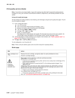
4512-420, -430 Dead machine service check CAUTION: Check the AC line voltage. The voltage should be within the following limits: • 100 V ac (volts alternating current) - 127 V ac for the 110 V printer • 200 V ac - 240 V ac for the 220 V printer FRU LVPS/HVPS Action Unplug the printer. Remove the LVPS/HVPS, and check the fuses for continuity. • If open, replace the LVPS/HVPS. • If not open, check the switch continuity across its conductors with the switch on. Turn the switch off. Plug the AC line into the LVPS/HVPS and switch unit on. Note: Voltages may be exposed at several places on the board. Do these verifications, and then unplug the card: • Verify 24 V dc on pins 8, 9, and 10 at PCN1. • Verify approximately 3V on pins 1-3. • Verify approximately 5V on pins 4 and 13. • If voltages are not correct, replace the LVPS/HVPS. • If voltages are correct, check the controller card. See "Controller card service check" on page 2-17. Fuser service check When toner is partially fused to the media, it is usually caused by low fuser temperature. The line voltage to the printer must be within the following limits: • 100 V ac-127 V ac for the 110 V model printer • 200 V ac-240 V ac for the 220 V model printer This printer uses a belt fuser and therefore does not have a lamp. Fuser service check FRU Fuser power cable LVPS/HVPS Fuser Fuser Action Unplug the printer, and disconnect the fuser cable plug from the LVPS/HVPS board connector at PCN5. Check for continuity across the fuser by checking across the connector pins. • If there is continuity, check the LVPS/HVPS. See "LVPS/HVPS service check" on page 3-20. • If there is no continuity, disconnect the fuser power cable at both ends and check each conductor for continuity. Replace cable if necessary. • If the cable tests good, replace the fuser. Make sure the fuser thermistor is correctly connected to the controller board at J13. If the problem persists, disconnect the thermistor cable and check for less than +5 V dc on pin 1. Pin 2 should be ground. If line voltage is incorrect on pin 1, see "Controller card service check" on page 2-17 for more information. Disconnect the thermistor cable from J13 on the controller card. Measure the resistance across the ends of the thermistor cable. Replace the fuser assembly if the resistance is lower than 1K ohm or shorted. Note: Resistance measures approximately 400K ohms when cool and 1K ohms hot. Diagnostics information 2-19
-
 1
1 -
2
-
3
-
4
-
5
-
6
-
7
-
8
-
9
-
10
-
11
-
12
-
13
-
14
-
15
-
16
-
17
-
18
-
19
-
20
-
21
-
22
-
23
-
24
-
25
-
26
-
27
-
28
-
29
-
30
-
31
-
32
-
33
-
34
-
35
-
 36
36 -
 37
37 -
 38
38 -
 39
39 -
 40
40 -
 41
41 -
 42
42 -
 43
43 -
 44
44 -
 45
45 -
 46
46 -
47
-
48
-
49
-
50
-
51
-
52
-
53
-
54
-
55
-
56
-
57
-
58
-
59
-
60
-
61
-
62
-
63
-
64
-
65
-
66
-
67
-
68
-
69
-
70
-
71
-
72
-
73
-
74
-
75
-
76
-
77
-
78
-
79
-
80
-
81
-
82
-
83
-
84
-
85
-
86
-
87
-
88
-
89
-
90
-
91
-
92
-
93
-
94
-
95
-
96
-
97
-
98
-
99
-
100
-
101
-
102
-
103
-
104
-
105
-
106
-
107
-
108
-
109
-
110
-
111
-
112
-
113
-
114
-
115
-
116
-
117
-
118
-
119
-
120
-
121
-
122
-
123
-
124
-
125
-
126
-
127
-
128
-
129
-
130
-
131
-
132
-
133
-
134
-
135
-
136
-
137
-
138
-
139
-
140
-
141
-
142
-
143
-
144
-
145
-
146
-
147
-
148
 |
 |
