Lexmark T630n Service Manual - Page 73
The printer does not recognize one or more output options as installed.
 |
UPC - 734646532211
View all Lexmark T630n manuals
Add to My Manuals
Save this manual to your list of manuals |
Page 73 highlights
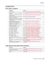
4060-xxx The printer does not recognize one or more output options as installed. Service tip: If more than a single output option is installed, check each one to see if the printer recognizes any single option as being installed. If the printer recognizes any of the output options then the base printer autoconnect system is operating correctly and the problem is in the unrecognized option. Continue with this service check or go to the service check for the failing output option. FRU 1 5-Bin mailbox option 2 Mechanical linkage assembly Action Check the autoconnects, cables, and connectors of the option for any signs of loose or damaged parts. Remove the left and right side covers and check the two autoconnects for damage, especially the connector pins. Remove the output option and check the voltages on the standard output bin autoconnect located on the top left rear of the printer. Go to "Autoconnect" on page 5-1. If the voltages are correct, reinstall the output option noting the position of the toroid on the autoconnect cable of the lower autoconnect. Check the voltages on each of the autoconnects. If the toroid was moved, make sure to move it back to its original position on the cable. If the voltages are correct, replace the control board. If the voltages are incorrect, replace the failing autoconnect assembly. 271 Paper Jam - Check Bin 1 displays FRU 1 Bottom pass thru sensor flag assembly Control board Action Check the flag for correct operation, binding, broken parts, or interference from the sensor cable. If incorrect, repair as necessary. If correct, make sure the bottom pass thru sensor is correctly connected to J5 on the control board. Disconnect the pass thru sensor cable and check the voltage at J5-3. The voltage measures approximately +5 V dc. If incorrect, check the voltage at J5-2. The voltage measures approximately 0 V dc. If incorrect, replace the sensor assembly. If this does not fix the problem, replace the control board. 274 Paper Jam - Check Bin 4 displays Service tip: When a 274 Paper Jam Check Bin 4 message displays, a problem exists with the top pass thru sensor assembly or the control board. FRU 1 Top pass thru sensor flag assembly Control board Action Check the flag for correct operation, binding, broken parts or interference from the sensor cable. If incorrect, repair as necessary. If correct check to make sure the top pass thru sensor is correctly connected to J11 on the control board. Disconnect the pass thru sensor cable and check the voltage at J11-3 The voltage measures approximately +5 V dc. If incorrect, check the voltage at J11-2. The voltage measures approximately 0 V dc. If incorrect, replace the sensor assembly. If this does not fix the problem, replace the lower control board. Diagnostic information 2-39
-
 1
1 -
2
-
3
-
4
-
5
-
6
-
7
-
8
-
9
-
10
-
11
-
12
-
13
-
14
-
15
-
16
-
17
-
18
-
19
-
20
-
21
-
22
-
23
-
24
-
25
-
26
-
27
-
28
-
29
-
30
-
31
-
32
-
33
-
34
-
35
-
36
-
37
-
38
-
39
-
40
-
41
-
42
-
43
-
44
-
45
-
46
-
47
-
48
-
49
-
50
-
51
-
52
-
53
-
54
-
55
-
56
-
57
-
58
-
59
-
60
-
61
-
62
-
63
-
64
-
65
-
66
-
67
-
 68
68 -
 69
69 -
 70
70 -
 71
71 -
 72
72 -
 73
73 -
 74
74 -
 75
75 -
 76
76 -
 77
77 -
 78
78 -
79
-
80
-
81
-
82
-
83
-
84
-
85
-
86
-
87
-
88
-
89
-
90
-
91
-
92
-
93
-
94
-
95
-
96
-
97
-
98
-
99
-
100
-
101
-
102
-
103
-
104
-
105
-
106
-
107
-
108
-
109
-
110
-
111
-
112
-
113
-
114
-
115
-
116
-
117
-
118
-
119
-
120
-
121
-
122
-
123
-
124
-
125
-
126
-
127
-
128
-
129
-
130
-
131
-
132
-
133
-
134
-
135
-
136
-
137
-
138
-
139
-
140
-
141
-
142
-
143
-
144
-
145
-
146
-
147
-
148
-
149
-
150
-
151
-
152
-
153
-
154
-
155
-
156
-
157
-
158
-
159
-
160
-
161
-
162
-
163
-
164
-
165
-
166
-
167
-
168
-
169
-
170
-
171
-
172
-
173
-
174
-
175
-
176
-
177
-
178
-
179
-
180
-
181
-
182
-
183
-
184
-
185
-
186
-
187
-
188
-
189
-
190
-
191
-
192
-
193
-
194
-
195
-
196
-
197
-
198
-
199
-
200
-
201
-
202
-
203
-
204
-
205
-
206
-
207
-
208
-
209
-
210
-
211
-
212
-
213
-
214
-
215
-
216
-
217
-
218
-
219
-
220
-
221
-
222
-
223
-
224
-
225
-
226
-
227
-
228
-
229
-
230
-
231
-
232
-
233
-
234
-
235
-
236
-
237
-
238
-
239
-
240
-
241
-
242
-
243
-
244
-
245
-
246
-
247
-
248
-
249
-
250
-
251
-
252
-
253
-
254
-
255
-
256
-
257
-
258
-
259
-
260
-
261
-
262
-
263
-
264
-
265
-
266
-
267
-
268
-
269
-
270
-
271
-
272
-
273
-
274
-
275
-
276
-
277
-
278
-
279
-
280
-
281
-
282
-
283
-
284
-
285
-
286
-
287
-
288
-
289
-
290
-
291
-
292
-
293
-
294
-
295
-
296
-
297
-
298
-
299
-
300
-
301
-
302
-
303
-
304
-
305
-
306
-
307
-
308
-
309
-
310
-
311
-
312
-
313
-
314
-
315
-
316
-
317
-
318
-
319
-
320
-
321
-
322
-
323
-
324
-
325
-
326
-
327
-
328
-
329
-
330
-
331
-
332
-
333
-
334
-
335
-
336
-
337
-
338
-
339
-
340
-
341
-
342
-
343
-
344
-
345
 |
 |
