Lexmark T640DTN Service Manual - Page 129
xx-Cold fuser check, CAUTION, EP SETUP, Fuser Temp
 |
UPC - 734646725224
View all Lexmark T640DTN manuals
Add to My Manuals
Save this manual to your list of manuals |
Page 129 highlights
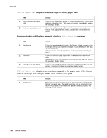
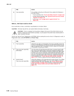
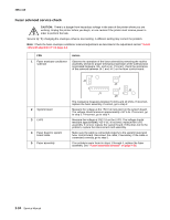
4061-xx0 922.xx-Cold fuser check Error codes 920.xx and 922.xx may display for a cold fuser failure. Some 920.xx error codes may be cleared by turning the printer on and off and allowing it to complete POR. CAUTION: There is a danger from hazardous voltage in the area of the printer where you are working. Unplug the printer before you begin, or use caution if the printer must receive power in order to perform the task. Service tip: Set the Fuser Temperature to NORMAL before starting this service check. In Diagnostics mode, select EP SETUP, and Fuser Temp. FRU 1 Fuser lamp 2 AC line voltage 3 LVPS 4 LVPS LVPS fuser AC cable 5 Fuser top cover assembly (thermistor, thermistor cable) Fuser to system board DC cable Action Remove the fuser assembly and check to make sure the correct fuser lamp has been installed. If the correct lamp has been installed, go to step 2. Note: If the fuser lamp is replaced, allow the fuser assembly to cool or a 925.xx error code could be displayed. CAUTION: When taking measurements for AC power, observe all safety precautions. Check the AC line voltage to make sure it is within operating specification. If incorrect, inform the customer; if correct, go to step 3. CAUTION: When taking measurements for AC power, observe all safety precautions. Unplug the AC line cord from the printer and pull the LVPS out far enough to access CN1 on the LVPS board (see "Low voltage power supply removal" on page 4-54). Disconnect the LVPS to fuser AC cable, plug in the line cord, turn the printer on and measure the voltage between CN1-1 and CN1-3 on the connector (see the connector locations at "Low voltage power supply removal" on page 4-54). If incorrect, replace the LVPS assembly (see "Low voltage power supply removal" on page 4-54); if correct, go to step 4. CAUTION: When taking measurements for AC power, observe all safety precautions. Disconnect the AC line cord from the printer. Disconnect the LVPS to fuser cable from the fuser to fuser lamp cable. Plug the AC line cord into the printer and check the AC line voltage between the pins on the fuser end of the LVPS to fuser AC cable. If the voltage is correct, unplug the AC power cord from the LVPS cable and pull the LVPS out far enough to be able to check the voltage between CN-1 and CN-3 on the LVPS board. Plug in the power cord, turn the printer on and check the voltage. If correct, replace the LVPS to fuser AC cable; if incorrect, replace the LVPS assembly. See "Low voltage power supply removal" on page 4-54. Note: If the fuses in the LVPS are blown, the LVPS assembly must be replaced. Check to make sure that the thermistor is installed correctly to J5 on the fuser control card. If installed correctly check the cable for any signs of damage. If any problems are found, replace the fuser top cover assembly."Fuser narrow media sensor removal" on page 4-34. If no problem is found, check the fuser to system board DC cable for correct installation at J1 on the fuser control card. If no problem is found, check the fuser to system board cable for correct installation at J10 on the system board. If no problem is found, go to step 6. Diagnostic information 2-89
-
 1
1 -
2
-
3
-
4
-
5
-
6
-
7
-
8
-
9
-
10
-
11
-
12
-
13
-
14
-
15
-
16
-
17
-
18
-
19
-
20
-
21
-
22
-
23
-
24
-
25
-
26
-
27
-
28
-
29
-
30
-
31
-
32
-
33
-
34
-
35
-
36
-
37
-
38
-
39
-
40
-
41
-
42
-
43
-
44
-
45
-
46
-
47
-
48
-
49
-
50
-
51
-
52
-
53
-
54
-
55
-
56
-
57
-
58
-
59
-
60
-
61
-
62
-
63
-
64
-
65
-
66
-
67
-
68
-
69
-
70
-
71
-
72
-
73
-
74
-
75
-
76
-
77
-
78
-
79
-
80
-
81
-
82
-
83
-
84
-
85
-
86
-
87
-
88
-
89
-
90
-
91
-
92
-
93
-
94
-
95
-
96
-
97
-
98
-
99
-
100
-
101
-
102
-
103
-
104
-
105
-
106
-
107
-
108
-
109
-
110
-
111
-
112
-
113
-
114
-
115
-
116
-
117
-
118
-
119
-
120
-
121
-
122
-
123
-
 124
124 -
 125
125 -
 126
126 -
 127
127 -
 128
128 -
 129
129 -
 130
130 -
 131
131 -
 132
132 -
 133
133 -
 134
134 -
135
-
136
-
137
-
138
-
139
-
140
-
141
-
142
-
143
-
144
-
145
-
146
-
147
-
148
-
149
-
150
-
151
-
152
-
153
-
154
-
155
-
156
-
157
-
158
-
159
-
160
-
161
-
162
-
163
-
164
-
165
-
166
-
167
-
168
-
169
-
170
-
171
-
172
-
173
-
174
-
175
-
176
-
177
-
178
-
179
-
180
-
181
-
182
-
183
-
184
-
185
-
186
-
187
-
188
-
189
-
190
-
191
-
192
-
193
-
194
-
195
-
196
-
197
-
198
-
199
-
200
-
201
-
202
-
203
-
204
-
205
-
206
-
207
-
208
-
209
-
210
-
211
-
212
-
213
-
214
-
215
-
216
-
217
-
218
-
219
-
220
-
221
-
222
-
223
-
224
-
225
-
226
-
227
-
228
-
229
-
230
-
231
-
232
-
233
-
234
-
235
-
236
-
237
-
238
-
239
-
240
-
241
-
242
-
243
-
244
-
245
-
246
-
247
-
248
-
249
-
250
-
251
-
252
-
253
-
254
-
255
-
256
-
257
-
258
-
259
-
260
-
261
-
262
-
263
-
264
-
265
-
266
-
267
-
268
-
269
-
270
-
271
-
272
-
273
-
274
-
275
-
276
-
277
-
278
-
279
-
280
-
281
-
282
-
283
-
284
-
285
-
286
-
287
-
288
-
289
-
290
-
291
-
292
-
293
-
294
-
295
-
296
-
297
-
298
-
299
-
300
-
301
-
302
-
303
-
304
-
305
-
306
-
307
-
308
-
309
-
310
-
311
-
312
-
313
-
314
-
315
-
316
-
317
-
318
-
319
-
320
-
321
-
322
-
323
-
324
-
325
-
326
-
327
-
328
-
329
-
330
-
331
-
332
-
333
-
334
-
335
-
336
-
337
-
338
-
339
-
340
-
341
-
342
-
343
-
344
-
345
-
346
-
347
-
348
-
349
-
350
-
351
-
352
-
353
-
354
-
355
-
356
-
357
-
358
-
359
-
360
-
361
-
362
-
363
-
364
-
365
-
366
-
367
-
368
-
369
-
370
-
371
-
372
-
373
-
374
-
375
-
376
-
377
-
378
-
379
-
380
-
381
-
382
-
383
-
384
-
385
-
386
-
387
-
388
-
389
-
390
-
391
-
392
-
393
-
394
-
395
-
396
-
397
-
398
-
399
-
400
-
401
-
402
-
403
-
404
-
405
-
406
-
407
-
408
-
409
-
410
-
411
-
412
-
413
-
414
-
415
-
416
-
417
-
418
-
419
-
420
-
421
-
422
 |
 |