Lexmark T640DTN Service Manual - Page 162
Printhead service check, Signature button assembly service check, CAUTION, Service error code
 |
UPC - 734646725224
View all Lexmark T640DTN manuals
Add to My Manuals
Save this manual to your list of manuals |
Page 162 highlights
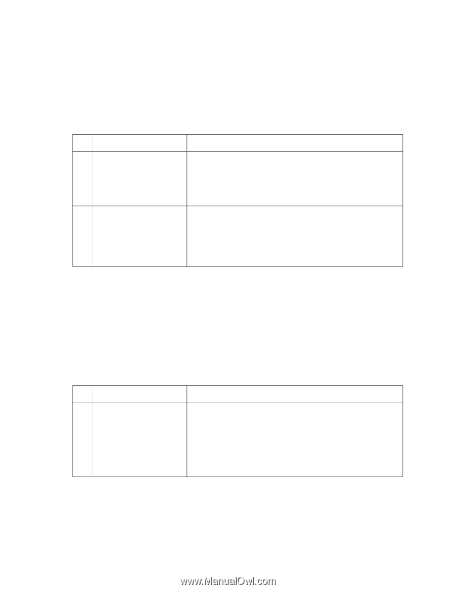
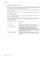
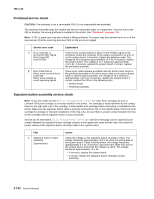
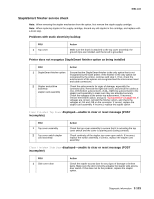
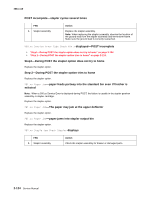
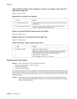
4061-xx0 Printhead service check CAUTION: The printhead is not a serviceable FRU. Do not disassemble the printhead. The printhead assembly does not contain any service replaceable parts or components. If service error code 930.xx displays, the wrong printhead is installed in the printer. See "Printhead" on page 7-10. Note: A 201.xx paper jam may also indicate a failing printhead. The paper may have jammed prior to or at the input sensor. Print the event log and see if 201 or 931 errors are logged. Service error code 1 Error code 931.xx No first HYSNC Signal Error Code 932 Lost HYSNC 2 Error Code 934.xx Mirror motor lost lock Error Code 935 Mirror motor unable to reach operating speed Explanation These errors usually indicate a failure in the HYSNC signal to the printhead. Check the continuity of the cables connected to J2 and J4 on the system board. If incorrect, replace the defective cable. The voltage at J4-1 measures approximately +5 V dc. If incorrect, replace the system board. The voltage at J2-7 measures approximately +24 V dc. If incorrect, replace the system board. If correct, replace the printhead assembly. These error codes indicate a problem with the mirror motor circuit in the printhead assembly or the mirror motor cable to the system board cable or system board assembly. The voltage at J5-2 measures approximately +24 V dc. If incorrect, replace the system board. If correct, replace the FRUs in the following order: • System board • Printhead assembly Signature button assembly service check Note: If you are unable to clear a 32.xx-Unsupported Cartridge User Error message, be sure a Lexmark T64x print cartridge is correctly installed in the printer. The cartridge is easily identified by the contact board on the right side rear of the cartridge. Install another print cartridge before attempting to troubleshoot the printer. Make sure the signature button cable is properly connected to J14 on the system board. Check the print cartridge for damage or improper installation of the chip. Also, be sure there is proper contact between the chip on the cartridge and the signature button contact assembly. Service tip: An intermittent 32.xx-Unsupported Cartridge User Error message can be caused by poor contact between the signature button cartridge contacts in the upper front cover and the chip. Also check for proper seating of the signature button cartridge cable to the system board. FRU 1 Signature button contact assembly System board Action Check the voltage on the signature button cartridge contact. The voltage measures approximately +3.8 V dc when not writing data to the system board. If data is being written, the voltage measures approximately 0 V dc. If incorrect, disconnect the cable from J19 on the system board, and check the voltage on J19-1. The voltage measures approximately +5 V dc. • If incorrect, replace the system board. • If correct, replace the signature button cartridge contact assembly. 2-122 Service Manual
-
 1
1 -
2
-
3
-
4
-
5
-
6
-
7
-
8
-
9
-
10
-
11
-
12
-
13
-
14
-
15
-
16
-
17
-
18
-
19
-
20
-
21
-
22
-
23
-
24
-
25
-
26
-
27
-
28
-
29
-
30
-
31
-
32
-
33
-
34
-
35
-
36
-
37
-
38
-
39
-
40
-
41
-
42
-
43
-
44
-
45
-
46
-
47
-
48
-
49
-
50
-
51
-
52
-
53
-
54
-
55
-
56
-
57
-
58
-
59
-
60
-
61
-
62
-
63
-
64
-
65
-
66
-
67
-
68
-
69
-
70
-
71
-
72
-
73
-
74
-
75
-
76
-
77
-
78
-
79
-
80
-
81
-
82
-
83
-
84
-
85
-
86
-
87
-
88
-
89
-
90
-
91
-
92
-
93
-
94
-
95
-
96
-
97
-
98
-
99
-
100
-
101
-
102
-
103
-
104
-
105
-
106
-
107
-
108
-
109
-
110
-
111
-
112
-
113
-
114
-
115
-
116
-
117
-
118
-
119
-
120
-
121
-
122
-
123
-
124
-
125
-
126
-
127
-
128
-
129
-
130
-
131
-
132
-
133
-
134
-
135
-
136
-
137
-
138
-
139
-
140
-
141
-
142
-
143
-
144
-
145
-
146
-
147
-
148
-
149
-
150
-
151
-
152
-
153
-
154
-
155
-
156
-
 157
157 -
 158
158 -
 159
159 -
 160
160 -
 161
161 -
 162
162 -
 163
163 -
 164
164 -
 165
165 -
 166
166 -
 167
167 -
168
-
169
-
170
-
171
-
172
-
173
-
174
-
175
-
176
-
177
-
178
-
179
-
180
-
181
-
182
-
183
-
184
-
185
-
186
-
187
-
188
-
189
-
190
-
191
-
192
-
193
-
194
-
195
-
196
-
197
-
198
-
199
-
200
-
201
-
202
-
203
-
204
-
205
-
206
-
207
-
208
-
209
-
210
-
211
-
212
-
213
-
214
-
215
-
216
-
217
-
218
-
219
-
220
-
221
-
222
-
223
-
224
-
225
-
226
-
227
-
228
-
229
-
230
-
231
-
232
-
233
-
234
-
235
-
236
-
237
-
238
-
239
-
240
-
241
-
242
-
243
-
244
-
245
-
246
-
247
-
248
-
249
-
250
-
251
-
252
-
253
-
254
-
255
-
256
-
257
-
258
-
259
-
260
-
261
-
262
-
263
-
264
-
265
-
266
-
267
-
268
-
269
-
270
-
271
-
272
-
273
-
274
-
275
-
276
-
277
-
278
-
279
-
280
-
281
-
282
-
283
-
284
-
285
-
286
-
287
-
288
-
289
-
290
-
291
-
292
-
293
-
294
-
295
-
296
-
297
-
298
-
299
-
300
-
301
-
302
-
303
-
304
-
305
-
306
-
307
-
308
-
309
-
310
-
311
-
312
-
313
-
314
-
315
-
316
-
317
-
318
-
319
-
320
-
321
-
322
-
323
-
324
-
325
-
326
-
327
-
328
-
329
-
330
-
331
-
332
-
333
-
334
-
335
-
336
-
337
-
338
-
339
-
340
-
341
-
342
-
343
-
344
-
345
-
346
-
347
-
348
-
349
-
350
-
351
-
352
-
353
-
354
-
355
-
356
-
357
-
358
-
359
-
360
-
361
-
362
-
363
-
364
-
365
-
366
-
367
-
368
-
369
-
370
-
371
-
372
-
373
-
374
-
375
-
376
-
377
-
378
-
379
-
380
-
381
-
382
-
383
-
384
-
385
-
386
-
387
-
388
-
389
-
390
-
391
-
392
-
393
-
394
-
395
-
396
-
397
-
398
-
399
-
400
-
401
-
402
-
403
-
404
-
405
-
406
-
407
-
408
-
409
-
410
-
411
-
412
-
413
-
414
-
415
-
416
-
417
-
418
-
419
-
420
-
421
-
422
 |
 |