LiftMaster CSL24UL Installation Manual - Page 16
Step 5 Earth Ground Rod, Step 6 Power Wiring, OPERATOR + ACCESSORIES POWERED BY TRANSFORMER KIT - solar panel
 |
View all LiftMaster CSL24UL manuals
Add to My Manuals
Save this manual to your list of manuals |
Page 16 highlights
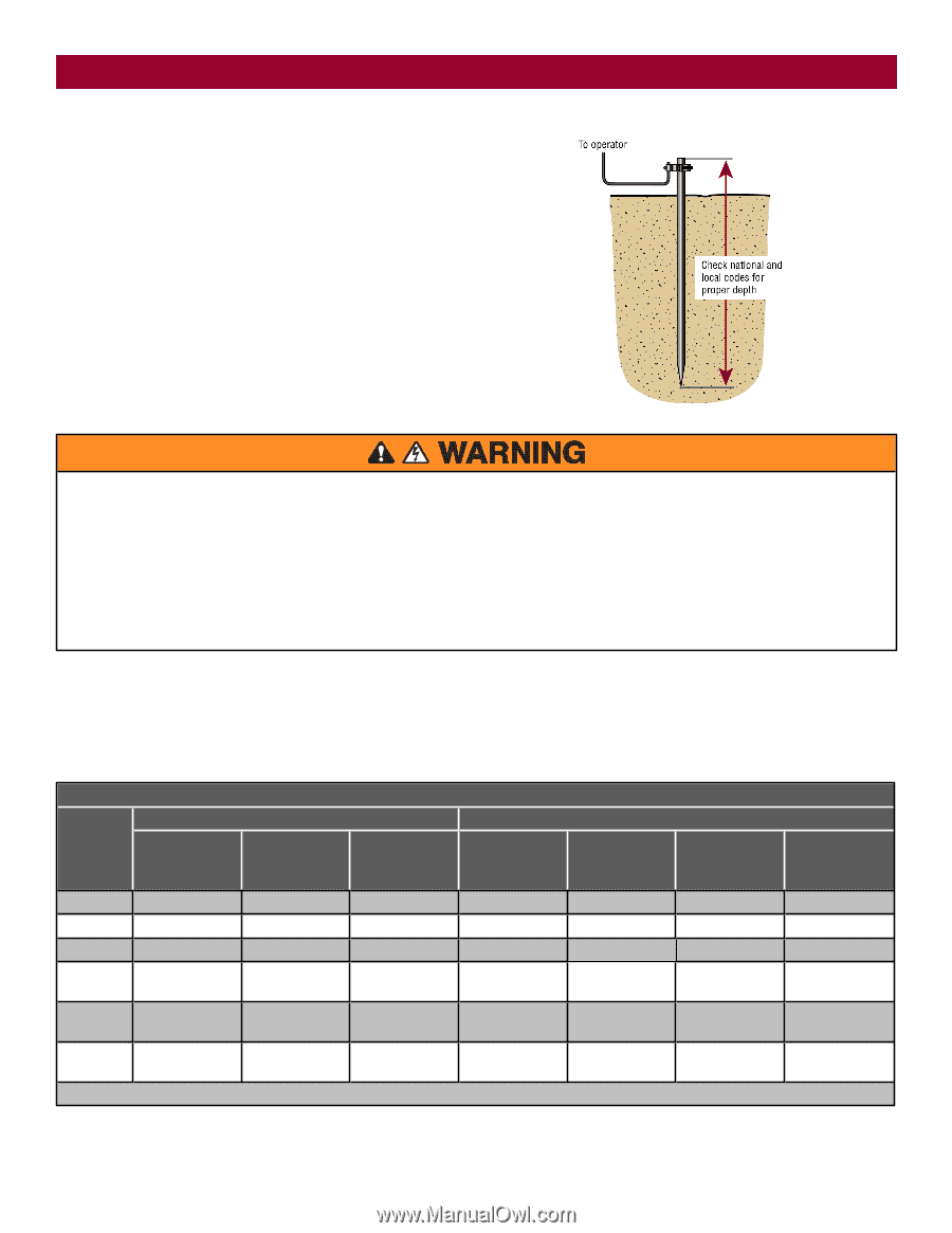
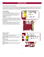
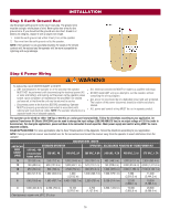
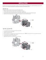
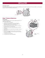
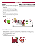
INSTALLATION Step 5 Earth Ground Rod Use the proper earth ground rod for your local area. The ground wire must be a single, whole piece of wire. Never splice two wires for the ground wire. If you should cut the ground wire too short, break it, or destroy its integrity, replace it with a single wire length. 1. Install the earth ground rod within 3 feet (.9 m) of the operator. 2. Run wire from the earth ground rod to the operator. NOTE: If the operator is not grounded properly the range of the remote controls will be reduced and the operator will be more susceptible to lightning and surge damage. Step 6 Power Wiring To reduce the risk of SEVERE INJURY or DEATH: l ANY maintenance to the operator or in the area near the operator l ALL electrical connections MUST be made by a qualified individual. MUST NOT be performed until disconnecting the electrical power (AC l DO NOT install ANY wiring or attempt to run the operator without or solar and battery) and locking-out the power via the operator power consulting the wiring diagram. switch. Upon completion of maintenance the area MUST be cleared and secured, at that time the unit may be returned to service. l ALL power wiring should be on a dedicated circuit and well protected. The location of the power disconnect should be visible and clearly l Disconnect power at the fuse box BEFORE proceeding. Operator labeled. MUST be properly grounded and connected in accordance with national and local electrical codes. NOTE: The operator should be on a l ALL power and control wiring MUST be run in separate conduit. separate fused line of adequate capacity. The operator can be wired for either 120 Vac or 240 Vac or a solar panel (not provided). Follow the directions according to your application. An optional Transformer Kit (Model 3PHCONV) can be used to change the input voltage (208/240/480/575 Vac) to an output voltage of 120 Vac (refer to Accessories). For dual gate applications, power will have to be connected to each operator. Main power supply and control wiring MUST be run in separate conduits. SOLAR APPLICATIONS: For solar applications refer to Solar Panels section in the Appendix. Follow the directions according to your application. NOTE: If using an external receiver use shielded wire for the connections and mount the receiver away from the operator to avoid interference from the operator. AMERICAN WIRE GAUGE (AWG) 14 MAXIMUM WIRE LENGTH STANDARD OPERATOR OPERATOR + ACCESSORIES POWERED BY TRANSFORMER KIT 120 VAC, 10A (includes fully loaded outlets) 120 VAC, 4A 240 VAC, 2A 208 VAC, 4.8A 240 VAC, 4.2A 480 VAC, 2.1A 575 VAC, 1.7A 100 (30.5 m) 250 (76.2 m) 1,000 (304.8 m) 360 (109.7 m) 480 (146.3 m) 1,900 (579.1 m) 2,800 (853.4 m) 12 160 (48.8 m) 400 (121.9 m) 1,600 (487.7 m) 570 (173.7 m) 750 (228.6 m) 3,000 (914.4 m) 4,500 (1,371.6 m) 10 250 (76.2 m) 630 (192 m) 2,500 (762 m) 900 (274.3 m) 1,200 (365.8 m) 4,800 (1,463 m) 7,100 (2,164.1 m) 8 400 (121.9 m) 1,000 (304.8 m) 4,000 1,400 (426.7 m) 1,900 (579.1 m) 7,600 11,300 (1,219.2 m) (2,316.5 m) (3,444.2 m) 6 636 (193.9 m) 1,600 (487.7 m) 6,400 (1950.7 m) 2,300 (701 m) 3,000 (914.4 m) 12,100 18,000 (3,688.1 m) (5,486.4 m) 4 1,000 (304.8 m) 2,500 (762 m) 10,100 3,700 4,800 (1,463 m) 19,300 28,500 (3,078.5 m) (1,127.8 m) (5,882.6 m) (8,686.8 m) Chart assumes: copper wire, 65°C, 5% drop 16
-
 1
1 -
2
-
3
-
4
-
5
-
6
-
7
-
8
-
9
-
10
-
 11
11 -
 12
12 -
 13
13 -
 14
14 -
 15
15 -
 16
16 -
 17
17 -
 18
18 -
 19
19 -
 20
20 -
 21
21 -
22
-
23
-
24
-
25
-
26
-
27
-
28
-
29
-
30
-
31
-
32
-
33
-
34
-
35
-
36
-
37
-
38
-
39
-
40
-
41
-
42
-
43
-
44
-
45
-
46
-
47
-
48
-
49
-
50
-
51
-
52
-
53
-
54
-
55
-
56
 |
 |