LiftMaster CSL24UL Installation Manual - Page 2

TABLE OF CONTENTS, SAFETY, Safety Symbol and Signal Word Review - parts

Page 2 highlights

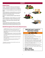
TABLE OF CONTENTS SAFETY 2 Safety Symbol and Signal Word Review 2 Usage Class 3 UL325 Entrapment Protection Requirements 3 Safety Installation Information 4 Gate Construction Information 5 INTRODUCTION 6 Carton Inventory 6 Operator Specifications 7 Site Preparation 8 INSTALLATION 9 Types of Installations 9 Step 1 Determine Location for Operator 10 Step 2 Install the Operator 11 Step 3 Attach the Chain 12 Step 4 Install Entrapment Protection 14 Step 5 Earth Ground Rod 16 Step 6 Power Wiring 16 Step 7 Connect Batteries 18 Step 8 Dual Gate Setup 20 Step 9 Install the Cover 22 ADJUSTMENT 23 Limit and Force Adjustment 23 Obstruction Test 24 PROGRAMMING 25 Remote Controls (Not Provided 25 LiftMaster Internet Gateway (not provided 26 Erase All Codes 26 Erase Limits 26 Constant Pressure Override (CPO 26 Gate Hold Open Feature 26 To Remove and Erase Monitored Entrapment Protection Devices 26 OPERATION 27 Gate Operator Setup Examples 27 Control Board Overview 28 Manual Disconnect 29 Reset Switch 29 Operator Alarm 29 Remote Control 29 ACCESSORY WIRING 30 External Control Devices 30 Locks 31 Miscellaneous Wiring 31 EXPANSION BOARD 32 Expansion Board Overview 32 Auxiliary Relay 1 and 2 33 Wiring Accessories to the Expansion Board 34 MAINTENANCE 35 Important Safety Instructions 35 Maintenance Chart 35 Batteries 36 Drive Train 36 TROUBLESHOOTING 37 Diagnostic Codes 37 Diagnostic Codes Table 38 Control Board LEDs 40 Troubleshooting Chart 41 APPENDIX 44 Step 6 Solar Panel(s 44 SAMS Wiring With Relays Not Energized 48 Dual Gate Settings 48 Limit Setup With a Remote Control 49 WIRING DIAGRAM 50 REPAIR PARTS 51 ACCESSORIES 52 WARRANTY 54 SAFETY Safety Symbol and Signal Word Review When you see these Safety Symbols and Signal Words on the following pages, they will alert you to the possibility of Serious Injury or Death if you do not comply with the warnings that accompany them. The hazard may come from something mechanical or from electric shock. Read the warnings carefully. When you see this Signal Word on the following pages, it will alert you to the possibility of damage to your gate and/or the gate operator if you do not comply with the cautionary statements that accompany it. Read them carefully. IMPORTANT NOTE: • BEFORE attempting to install, operate or maintain the operator, you must read and fully understand this manual and follow all safety instructions. • DO NOT attempt repair or service of your gate operator unless you are an Authorized Service Technician. MECHANICAL ELECTRICAL WARNING: This product can expose you to chemicals including lead, which are known to the State of California to cause cancer or birth defects or other reproductive harm. For more information go to www.P65Warnings.ca.gov. 2

  • 1
  • 2
  • 3
  • 4
  • 5
  • 6
  • 7
  • 8
  • 9
  • 10
  • 11
  • 12
  • 13
  • 14
  • 15
  • 16
  • 17
  • 18
  • 19
  • 20
  • 21
  • 22
  • 23
  • 24
  • 25
  • 26
  • 27
  • 28
  • 29
  • 30
  • 31
  • 32
  • 33
  • 34
  • 35
  • 36
  • 37
  • 38
  • 39
  • 40
  • 41
  • 42
  • 43
  • 44
  • 45
  • 46
  • 47
  • 48
  • 49
  • 50
  • 51
  • 52
  • 53
  • 54
  • 55
  • 56

2
SAFETY
2
Safety Symbol and Signal Word Review
................................................
2
Usage Class
...........................................................................................
3
UL325 Entrapment Protection Requirements
........................................
3
Safety Installation Information
...............................................................
4
Gate Construction Information
...............................................................
5
INTRODUCTION
6
Carton Inventory
....................................................................................
6
Operator Specifications
..........................................................................
7
Site Preparation
.....................................................................................
8
INSTALLATION
9
Types of Installations
.............................................................................
9
Step 1 Determine Location for Operator
..............................................
10
Step 2 Install the Operator
...................................................................
11
Step 3 Attach the Chain
.......................................................................
12
Step 4 Install Entrapment Protection
...................................................
14
Step 5 Earth Ground Rod
.....................................................................
16
Step 6 Power Wiring
............................................................................
16
Step 7 Connect Batteries
.....................................................................
18
Step 8 Dual Gate Setup
........................................................................
20
Step 9 Install the Cover
.......................................................................
22
ADJUSTMENT
23
Limit and Force Adjustment
.................................................................
23
Obstruction Test
..................................................................................
24
PROGRAMMING
25
Remote Controls (Not Provided)
.........................................................
25
LiftMaster Internet Gateway (not provided)
.........................................
26
Erase All Codes
....................................................................................
26
Erase Limits
.........................................................................................
26
Constant Pressure Override (CPO)
......................................................
26
Gate Hold Open Feature
.......................................................................
26
To Remove and Erase Monitored
Entrapment Protection Devices
............................................................
26
OPERATION
27
Gate Operator Setup Examples
............................................................
27
Control Board Overview
.......................................................................
28
Manual Disconnect
..............................................................................
29
Reset Switch
........................................................................................
29
Operator Alarm
....................................................................................
29
Remote Control
....................................................................................
29
ACCESSORY WIRING
30
External Control Devices
......................................................................
30
Locks
...................................................................................................
31
Miscellaneous Wiring
...........................................................................
31
EXPANSION BOARD
32
Expansion Board Overview
..................................................................
32
Auxiliary Relay 1 and 2
........................................................................
33
Wiring Accessories to the Expansion Board
........................................
34
MAINTENANCE
35
Important Safety Instructions
..............................................................
35
Maintenance Chart
...............................................................................
35
Batteries
...............................................................................................
36
Drive Train
...........................................................................................
36
TROUBLESHOOTING
37
Diagnostic Codes
.................................................................................
37
Diagnostic Codes Table
.......................................................................
38
Control Board LEDs
.............................................................................
40
Troubleshooting Chart
.........................................................................
41
APPENDIX
44
Step 6 Solar Panel(s)
...........................................................................
44
SAMS Wiring With Relays Not Energized
............................................
48
Dual Gate Settings
...............................................................................
48
Limit Setup With a Remote Control
.....................................................
49
WIRING DIAGRAM
50
REPAIR PARTS
51
ACCESSORIES
52
WARRANTY
54
Safety Symbol and Signal Word Review
WARNING:
This product can expose you to chemicals including lead, which are known to the State of California to cause cancer or birth defects
or other reproductive harm. For more information go to
www.P65Warnings.ca.gov
.
When you see these Safety Symbols and Signal Words on the following pages, they will alert
you to the possibility of
Serious Injury or Death
if you do not comply with the warnings that
accompany them. The hazard may come from something mechanical or from electric shock.
Read the warnings carefully.
When you see this Signal Word on the following pages, it will alert you to the possibility of
damage to your gate and/or the gate operator if you do not comply with the cautionary
statements that accompany it. Read them carefully.
IMPORTANT NOTE:
BEFORE attempting to install, operate or maintain the operator, you must read and fully
understand this manual and follow all safety instructions.
DO NOT attempt repair or service of your gate operator unless you are an Authorized
Service Technician.
MECHANICAL
ELECTRICAL
TABLE OF CONTENTS
SAFETY