LiftMaster LM21XP LM21XP Manual
LiftMaster LM21XP Manual
 |
View all LiftMaster LM21XP manuals
Add to My Manuals
Save this manual to your list of manuals |
LiftMaster LM21XP manual content summary:
- LiftMaster LM21XP | LM21XP Manual - Page 1
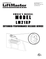
The Chamberlain Group, Inc. 845 Larch Avenue Elmhurst, Illinois 60126-1196 www.liftmaster.com OWNER'S MANUAL MODEL LM21XP EXTENDED PERFORMANCE RELEASE DEVICE - LiftMaster LM21XP | LM21XP Manual - Page 2
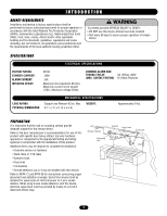
to install, operate or maintain the release device, you must read and fully understand this manual and follow all safety instructions. • DO NOT attempt repair or service of your release device unless you are an Authorized Service Technician. INTRODUCTION GENERAL DESCRIPTION The LiftMaster® LM21XP - LiftMaster LM21XP | LM21XP Manual - Page 3
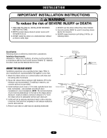
surface provide adequate support for the release device. Refer to the door manufacturer's recommendations for use of this product with specific door being utilized. Use only hardware approved or recognized by the appropriate testing and listing agencies in conjunction with the installation of this - LiftMaster LM21XP | LM21XP Manual - Page 4
reduce the risk of SEVERE INJURY or DEATH: 1. READ AND FOLLOW ALL INSTALLATION WARNINGS AND INSTRUCTIONS. 2. NEVER connect release device to power source until instructed to do so. 3. DO NOT install this device on a motorized door without an electric safety edge. 4. DO NOT use this device without - LiftMaster LM21XP | LM21XP Manual - Page 5
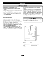
length and wiring methods. WIRING INSTRUCTIONS Verify wiring configuration with that recommended by door manufacturer for use of this product with specific door and accessories being utilized. 18-gauge wire is recommended. 1. Turn off power supply sources for the release device as well as the - LiftMaster LM21XP | LM21XP Manual - Page 6
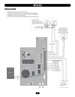
D1 U3 014G0962B PTC1 Input Power (4) LED4 LED5 LED6 LED2 LED7 2W_OP 2W_FAULT NC_FAULT CL_LIMIT GND_FAULT Common Relay Connections Alarm NC Alarm Com Alarm NO Trouble NC Trouble Com Trouble NO K3 K1 (YE) (GY) P1 + SW2 SW3 POWER ON LED 1 DISABLE LED 3 N.O. Close - LiftMaster LM21XP | LM21XP Manual - Page 7
smoke detectors or signaling for simultaneous closure on multiple doors, call technical support, 1-888-528-7870. Incorrect wiring between devices may cause damage to the release control circuit and void warranty. OR Relay Module Installation as described on the following page. WARNING To prevent - LiftMaster LM21XP | LM21XP Manual - Page 8
to provide a signal at the panel that the release device is in a trouble state (Figure 9). If these features are desired, coordinate the interconnection between the Release Device and the Fire Alarm Control Panel with the fire alarm installer. 7 Attach to Common on N/O Proximity Switch 8 Attach - LiftMaster LM21XP | LM21XP Manual - Page 9
fusible link chain upon alarm or power loss. A 4-position DIP Switch found on the PC board within the release device can be used to adjust the length of the delay to one of four preset delays. The optional delay settings are as follows: Delay - LiftMaster LM21XP | LM21XP Manual - Page 10
POWER 1. Make sure door is in fully open position. Turn off all power to release device. Immediately upon loss of power to the release device, a mechanical release will be initiated. 2. Reset the door per door manufacturer's instructions. Raise the door and then reset the release device by pushing - LiftMaster LM21XP | LM21XP Manual - Page 11
to reset, then depress the auxiliary reset button to reset. Refer to the Smoke Detector Installation section on pages 7 and 8 of this manual for correct wiring instructions. If lit, indicates that the fire door or shutter is closed and activating the proximity switch. If not lit, refer to the - LiftMaster LM21XP | LM21XP Manual - Page 12
attached to terminal positions 7 and 8 on the release device. Power Red If the Red LED is lit, then the line power is connected and If the LED does not light when power is applied, check switched "on." that power is connected as described in the installation manual electrical connections. 12 - LiftMaster LM21XP | LM21XP Manual - Page 13
End Link 01-32046 Owner's Manual LMEOLRES-10 End-of-Line Resistor, 10 kOhm NOTE: Certain accessories above will require a separate power source. Refer to product manual. HOW TO ORDER REPAIR PARTS OUR LARGE SERVICE ORGANIZATION SPANS AMERICA Installation and service information call our TOLL FREE - LiftMaster LM21XP | LM21XP Manual - Page 14
APPENDIX ACCESSORY COMPATIBILITY GUIDE SMOKE DETECTORS MODEL NO. DESCRIPTION LM2W-B LM2WT-B LM4W-B LM4WT-B LM1424 ) MODEL NO. #283B-PL #284B-PL SPACE AGE ELECTRONICS NO. PAM-1 LIFTMASTER NO. LMEOLRES-10 NOTE: Certain accessories above will require a separate power source. Refer to product - LiftMaster LM21XP | LM21XP Manual - Page 15
OPERATOR NOTES 15 - LiftMaster LM21XP | LM21XP Manual - Page 16
01-32046B Issue Date 7/27/2006 © 2006, The Chamberlain Group, Inc. All Rights Reserved
-
 1
1 -
 2
2 -
 3
3 -
 4
4 -
 5
5 -
 6
6 -
 7
7 -
8
-
9
-
10
-
11
-
12
-
13
-
14
-
15
-
16
 |
 |
O W N E R ’ S M A N U A L
MODEL
LM21XP
EXTENDED PERFORMANCE RELEASE DEVICE
The Chamberlain Group, Inc.
845 Larch Avenue
Elmhurst, Illinois 60126-1196
www.liftmaster.com