LiftMaster LM21XP LM21XP Manual - Page 11
Troubleshooting
 |
View all LiftMaster LM21XP manuals
Add to My Manuals
Save this manual to your list of manuals |
Page 11 highlights
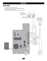
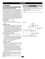
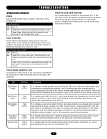
TROUBLESHOOTING OPERATIONAL CHECKLIST POWER Is the red LED, labeled "Power," located on the bottom of the enclosure lit? Is the Red LED Lit? Yes Move on. No Check power connections at terminal board positions 1 and 2. Check voltage; voltage should be 24Vdc received from an approved UL 1481 regulated power supply. CHECK THE ALARM Are the alarm (smoke detection) inputs correct? If not, the release device will not release the fusible link assembly in a fire condition. Conversely, the release device will always release the fusible link assembly when powered or reset. Are the Alarm Inputs correct? Yes Move on. No Check that it is a dry contact input. There should not be any voltage on the alarm lines when they are disconnected from the unit. Check to see if it is tied into an addressable relay module of an alarm panel. At times, noise can be picked up from these modules. CHECK THE CLOSE DOOR DETECTION Is the Yellow LED on the bottom of the enclosure lit? If lit, the close limit is active and the device is disabled and will not release the tension on the door spring as the door is in the closed position, activating the proximity switch. If not lit, check wiring instructions in Figure 8. CIRCUIT BOARD DIAGNOSTIC LEDS View diagnostic LEDs present on the circuit board located behind the terminal board. Refer to the table below for the status LED indications. LED N/O Detector Trouble N/O Detector Alarm N/C Detector Trouble Close Door Detection Ground Fault LED Color Yellow (LED 4) Red (LED 5) Red (LED 6) Green (LED 2) Yellow (LED 7) Description If lit, indicates a trouble condition (a short) within the N/O 2-wire (or 4-wire) smoke detector loop (emanating from terminal board positions 3 and 4), resulting from either incorrect wiring or incorrect placement of the end-of-line resistor, and the smoke detector loop is inactive. Refer to the Smoke Detector Installation section on pages 7 and 8 of this manual for correct wiring instructions. If lit, indicates that the N/O 2-wire (or 4-wire) smoke detector loop (emanating from terminal board positions 3 and 4) is in alarm. When lit during testing, press the Auxiliary Reset Button at the bottom of the release device to reset the loop. If lit, indicates an open circuit within the N/C 4-wire smoke detector loop (emanating from terminal board positions 5 and 6), resulting from either incorrect wiring or incorrect placement of the endof-line relay or the detector(s) are in alarm. If in alarm, cycle power off and then on to the smoke detectors to reset, then depress the auxiliary reset button to reset. Refer to the Smoke Detector Installation section on pages 7 and 8 of this manual for correct wiring instructions. If lit, indicates that the fire door or shutter is closed and activating the proximity switch. If not lit, refer to the Close Door Detection section of this manual for correct wiring instructions. If lit, indicates that one of the ancillary devices/loops (smoke detector, annunciator, etc.) is not grounded properly, and a short to earth ground exists. 11
-
 1
1 -
2
-
3
-
4
-
5
-
 6
6 -
 7
7 -
 8
8 -
 9
9 -
 10
10 -
 11
11 -
 12
12 -
 13
13 -
 14
14 -
 15
15 -
 16
16
 |
 |
