LiftMaster LM21XP LM21XP Manual - Page 6
Wiring Diagram
 |
View all LiftMaster LM21XP manuals
Add to My Manuals
Save this manual to your list of manuals |
Page 6 highlights
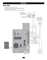
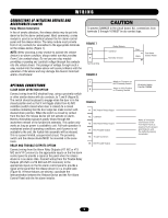
WIRING WIRING DIAGRAM Field Wiring shall consist of 22-18 AWG wiring. 1. Supervised, power limited circuit, 20 Ohm maximum line impedance. 2. Unsupervised, power limited circuit, 20 Ohm maximum line impedance. 3. Maximum of 4 Class B Style A detectors. 4. Power from an approved UL1481 regulated supply with battery backup. 2-Wire Detector Initiation Loop (1) (3) Keep 10k Ohm resister between 5 & 6 if unused. Resistor 10k Ohm EOL + In + Out - In/Out + In + Out - In/Out Normally Closed Initiation Loop (1) (3) Keep jumper between 3 & 4 if unused. External power required. 16 15 14 13 12 11 10 9 8 7 6 5 4 3 2 1 + 24Vdc NC COM Solenoid 1234 U4 P2 R6 C4 C2 U2 C1 SW1 K2 D1 U3 014G0962B PTC1 Input Power (4) LED4 LED5 LED6 LED2 LED7 2W_OP 2W_FAULT NC_FAULT CL_LIMIT GND_FAULT Common Relay Connections Alarm NC Alarm Com Alarm NO Trouble NC Trouble Com Trouble NO K3 K1 (YE) (GY) P1 + SW2 SW3 POWER ON LED 1 DISABLE LED 3 N.O. Close Door Proximity Switch (2) 6
-
 1
1 -
 2
2 -
 3
3 -
 4
4 -
 5
5 -
 6
6 -
 7
7 -
 8
8 -
 9
9 -
 10
10 -
 11
11 -
 12
12 -
13
-
14
-
15
-
16
 |
 |
