LiftMaster MJ MJ (BLACK LINE) Manual - Page 10
TEST THE SYSTEM, BRAKE ADJUSTMENT, IMPORTANT NOTES, Solenoid Brake System - parts
 |
View all LiftMaster MJ manuals
Add to My Manuals
Save this manual to your list of manuals |
Page 10 highlights
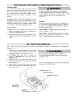
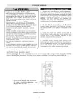
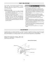
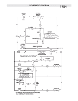
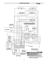
WARNING TEST THE SYSTEM WARNING CAUTION Turn on power. Test all controls and safety devices to make sure they are working properly. It will be necessary to refer back to page 6 for fine adjustment of the limit switches. IMPORTANT NOTES: • Do not leave operator power on unless all safety and entrapment protection devices have been tested and are working properly. • Be sure you have read and understand all Safety Instructions included in this manual. • Be sure the owner or person(s) responsible for operation of the door have read and understand the Safety Instructions, know how to electrically operate the door in a safe manner, and know how to use the manual disconnect operation of the door operating system. WARNING To reduce the risk of SEVERE INJURY or DEATH: • ANY maintenance to the operator or in the area near the operator MUST NOT be performed until disconnecting the electrical power and locking-out the power via the operator power switch. Upon completion of maintenance the area MUST be cleared and secured, at that time the unit may be returned to service. • Disconnect power at the fuse box BEFORE proceeding. Operator MUST be properly grounded and connected in accordance with local electrical codes. The operator should be on a separate fused line of adequate capacity. • All electrical connections MUST be made by a qualified individual. • DO NOT install ANY wiring or attempt to run the operator without consulting the wiring diagram. We recommend that you install an optional reversing edge BEFORE proceeding with the control station installation. • ALL power wiring should be on a dedicated circuit and well protected. The location of the power disconnect should be visible and clearly labeled. • ALL power and control wiring MUST be run in separate conduit. ADJUSTMENT A solenoid brake is an optional modification. If present, the brake is adjusted at the factory and should not need additional adjustment for the the life of the friction pad. If desired, a brake can also be field installed. To order a kit for field installation on an existing operator, call the parts and service department at 1-800-528-2806. Replace friction pads when necessary. Refer to the illustration for identification of components for the solenoid type brake system. Solenoid Brake System Solenoid Release Lever Friction Pad Pulley 10
-
 1
1 -
2
-
3
-
4
-
 5
5 -
 6
6 -
 7
7 -
 8
8 -
 9
9 -
 10
10 -
 11
11 -
 12
12 -
 13
13 -
 14
14 -
 15
15 -
16
-
17
-
18
-
19
-
20
-
21
-
22
-
23
-
24
 |
 |