LiftMaster MJ MJ (BLACK LINE) Manual - Page 9
CLUTCH ADJUSTMENT, Additional Access Control Equipment - model
 |
View all LiftMaster MJ manuals
Add to My Manuals
Save this manual to your list of manuals |
Page 9 highlights
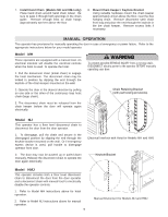
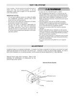
CONTROL WIRING (cont'd) WARNING WARNWINAGRNING Install the control station and receiver where the door is To prevent possible SERIOUS INJURY or DEATH from a moving CAUTION visible, but away from the door and its hardware. When a receiver is used to activate a commercial door opener, a reversing edge MUST be installed on the bottom of the door. Failure to install a reversing edge under these circumstances may result in SERIOUS INJURY or DEATH to persons trapped beneath the door. CAUTIWONARNING gate or garage door: • ALWAYS keep remote controls out of reach of children. NEVER permit children to operate, or play with remote controls. • Activate gate or door ONLY when it can be seen clearly, is properly adjusted, and there are no obstructions to door travel. Radio Controls On all models with type C2 control wiring, a terminal • ALWAYS keep gate or garage door in sight until completely closed. NEVER permit anyone to cross path of moving gate or door. bracket marked R1 R2 R3 is located on the outside of the electrical enclosure. All standard radio receivers (single channel residential type) may be mounted to this bracket. The operator will then open a fully closed door, close a fully open door, and reverse a closing door from the radio transmitter. However, for complete door control from a remote, a commercial three-channel radio receiver (with connections for OPEN/CLOSE/STOP) is recommended. Additional Access Control Equipment Locate any additional access control equipment as desired (but so that the door will be in clear sight of the person operating the equipment), and connect to the terminal block in the electrical enclosure as shown on the FIELD WIRING CONNECTIONS diagram. Any control with a normally (N.O.) isolated output contact may be connected in parallel with the OPEN button. More than one device may be connected in this manner. Use 16 gauge wire or larger for all controls. DO NOT USE THE CONTROL CIRCUIT TRANSFORMER (24VAC) IN THE OPERATOR TO POWER ANY ACCESS CONTROL EQUIPMENT OTHER THAN A STANDARD RESIDENTIAL TYPE RADIO RECEIVER. External Interlock Switch The operator has a terminal connection for an external interlock switch. This switch must be a normally closed (N.C.) two-wire device with a contact rating of at least 3 amps @ 24VAC. When such a switch is connected as shown on the FIELD WIRING CONNECTIONS diagram, the control circuit will be disabled when the switch is actuated, thereby preventing electrical operation of the door from the control devices. CLUTCH ADJUSTMENT 1. Remove cotterpin from nut on the clutch shaft. 2. Back off clutch nut until there is very little tension on the clutch spring. 3. Tighten clutch nut gradually until there is just enough tension to permit the operator to move the door smoothly but to allow the clutch to slip if the door is obstructed. When the clutch is properly adjusted, it should generally be possible to stop the door by hand during travel. 4. Reinstall cotterpin. WARNING To prevent possible SERIOUS INJURY or DEATH, install CAUTION reversing sensors when the 3-button control station is out of sight of the door or any other control (automatic or manual) is used. Reversing devices are recommended for ALL installations. Adjusting Nut Spring Clutch Pad Clutch Plate NOTE: The adjustable friction clutch is NOT an automatic reversing device. An electric or pneumatic reversing edge can be added to bottom edge of door if desired. 9 Cotterpin Washer Clutch Pulley
-
 1
1 -
2
-
3
-
 4
4 -
 5
5 -
 6
6 -
 7
7 -
 8
8 -
 9
9 -
 10
10 -
 11
11 -
 12
12 -
 13
13 -
 14
14 -
15
-
16
-
17
-
18
-
19
-
20
-
21
-
22
-
23
-
24
 |
 |