LiftMaster MJ MJ (BLACK LINE) Manual - Page 24
Control Connection Diagram, Important Notes
 |
View all LiftMaster MJ manuals
Add to My Manuals
Save this manual to your list of manuals |
Page 24 highlights
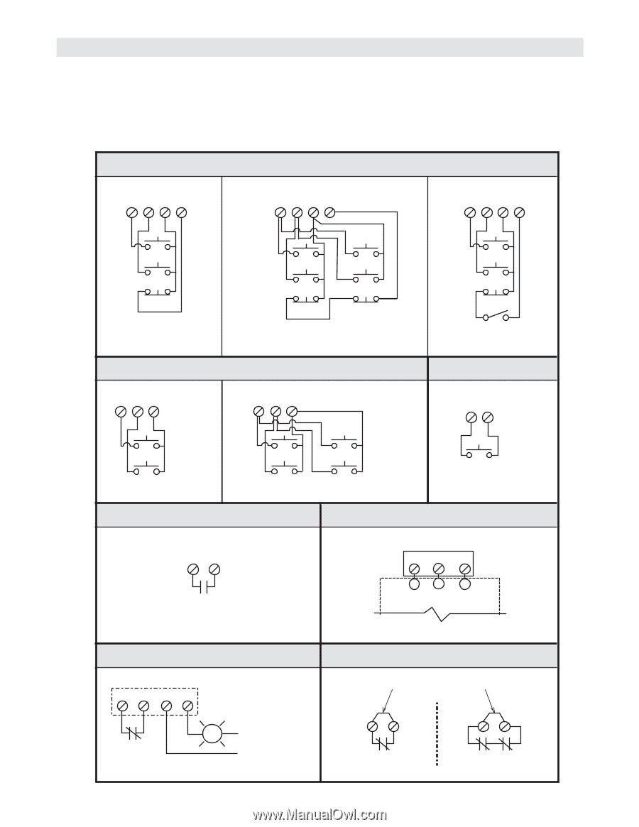
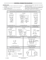
CONTROL CONNECTION DIAGRAM IMPORTANT NOTES: 1) The 3-Button Control Station provided must be connected for operation. 2) If a STOP button is not used, a jumper must be placed between terminals 3 and 4. 3) Auxiliary control equipment may be any normally open two wire device such as pullswitch, single button, loop detector, card key or such device. 4) When adding accessories, install them one at a time and test each one after it is added to ensure proper installation and operation with the Commercial Door Operator. 5) Use 16 gauge or heavier wire for all control circuit wiring. 3 BUTTON STATION or 3 POSITION KEYSWITCH w/ SPRING RETURN TO CENTER AND STOP BUTTON STANDARD 1234 2 OR MORE 1234 KEY LOCKOUT 1234 Open Close Stop Open Close Stop Open Close Stop Open Close Stop Keyswitch ALL CONTROL WIRING TYPES ALL CONTROL WIRING TYPES 2 BUTTON STATION or 3 POSITION KEYSWITCH w/ SPRING RETURN TO CENTER STANDARD 124 2 OR MORE 124 SEE NOTE #2 SEE NOTE #2 ALL CONTROL WIRING TYPES 1 BUTTON STATION or ANY AUXILIARY DEVICE 37 SEE NOTES #2 AND #3 Open Close ALL CONTROL WIRING TYPES Open Open Close Close ALL CONTROL WIRING TYPES OPEN / CLOSE B2 or T1 WIRING TYPES ONLY SENSING DEVICE TO REVERSE OR STOP RESIDENTIAL RADIO CONTROLS 3 10 *OPEN TIMER TO CLOSE R1 R2 R3 EXTERNAL TERMINAL BLOCK Sensing Device RADIO CONTROL ALL CONTROL WIRING TYPES TIMER TO CLOSE w/ WARNING LIGHT ALL CONTROL WIRING TYPES * T1 WIRING - RADIO TO OPEN ONLY EXTERNAL INTERLOCK Warning Light will activate 15 sec. before door closes. 11 12 13 14 Auxiliary Terminal Block Remove Jumper When Interlock is Used 4 5 4 5 Timer Defeat Switch Power Supply for Warning Light T1 CONTROL WIRING ONLY ONE 2 OR MORE ALL CONTROL WIRING TYPES 01-10701M ©2006, The Chamberlain Group, Inc. All rights Reserved
-
 1
1 -
2
-
3
-
4
-
5
-
6
-
7
-
8
-
9
-
10
-
11
-
12
-
13
-
14
-
15
-
16
-
17
-
18
-
 19
19 -
 20
20 -
 21
21 -
 22
22 -
 23
23 -
 24
24
 |
 |